Road surface frictional coefficient estimating apparatus

a technology of friction coefficient and estimating apparatus, which is applied in the field of road surface friction coefficient estimating apparatus, can solve the problems of difficult accurate detection or estimation of the state amount of the side slip motion of the vehicle, easy fluctuation of the lateral acceleration difference or the yaw rate change velocity difference, and inability to accurately reflect the value of

Active Publication Date: 2012-11-20
HONDA MOTOR CO LTD
View PDF18 Cites 4 Cited by
  • Summary
  • Abstract
  • Description
  • Claims
  • Application Information

AI Technical Summary

Benefits of technology

[0012]The present invention has been made in view of the background described above, and an object of the present invention is to provide a road surface frictional coefficient estimating apparatus capable of accurately and stably estimating the frictional coefficient of a road surface on which a vehicle is traveling and also capable of accomplishing estimation processing with high robustness.

Problems solved by technology

The value of the state amount of a side slip motion of a vehicle is generally difficult to accurately detect or estimate.
Hence, the aforesaid lateral acceleration difference and the yaw rate change velocity difference are apt to be influenced by the estimation error of the state amount of the side slip motion of the vehicle or a bank angle in addition to an error of an estimated value of μ. This means that even if an estimated value of μ accurately coincides with an actual value, the lateral acceleration difference or the yaw rate change velocity difference easily fluctuates due to the influences of an estimation error of the state amount of the side slip motion of the vehicle or a bank angle.
As a result, even if the estimated value of μ is updated according to the lateral acceleration difference or the yaw rate change velocity difference, the error of an estimated value of μ will not be properly reflected, making it difficult to accurately and stably determine the estimated value of μ in some cases.

Method used


Image

  • Road surface frictional coefficient estimating apparatus
  • Road surface frictional coefficient estimating apparatus
  • Road surface frictional coefficient estimating apparatus

Examples


first embodiment

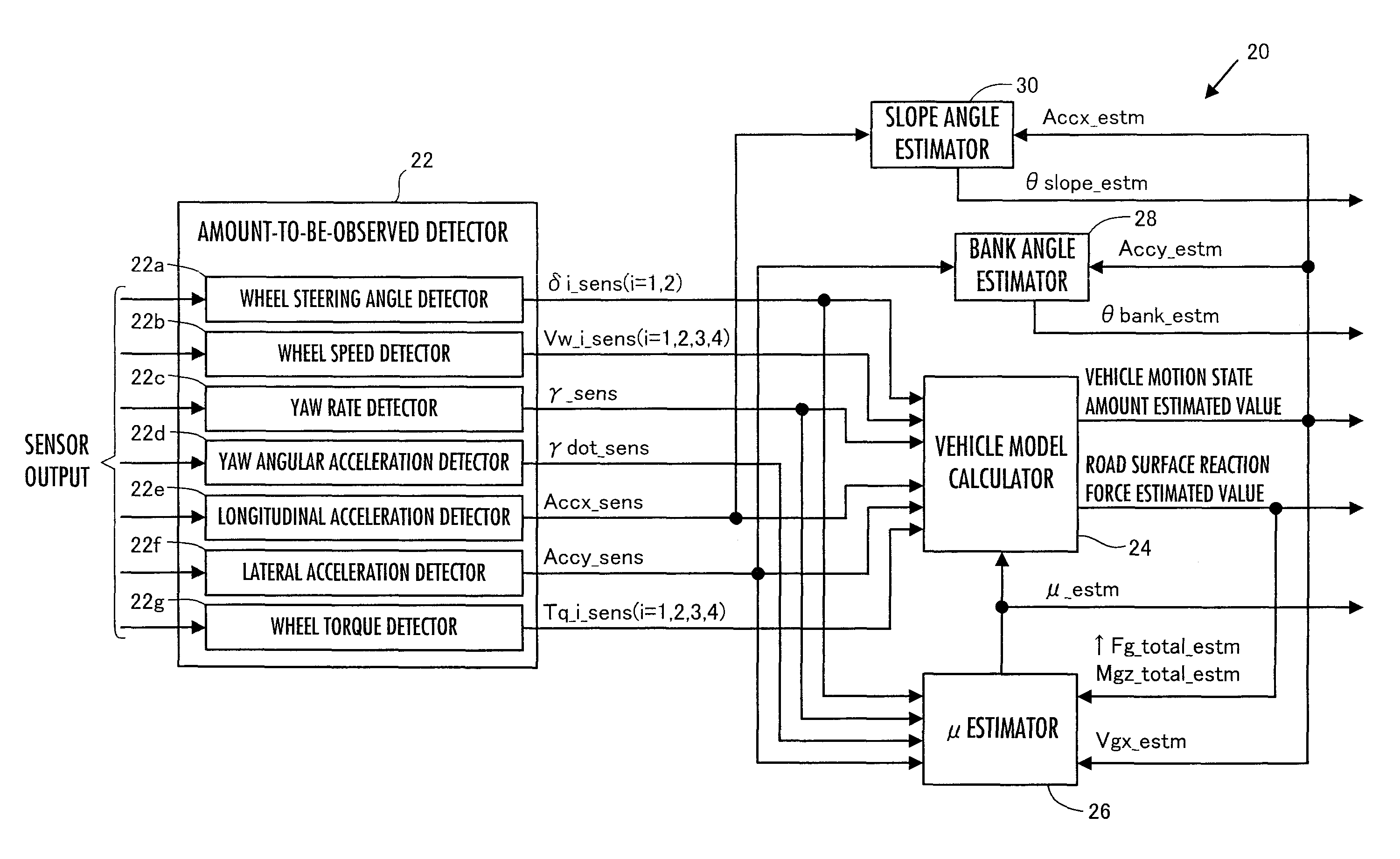
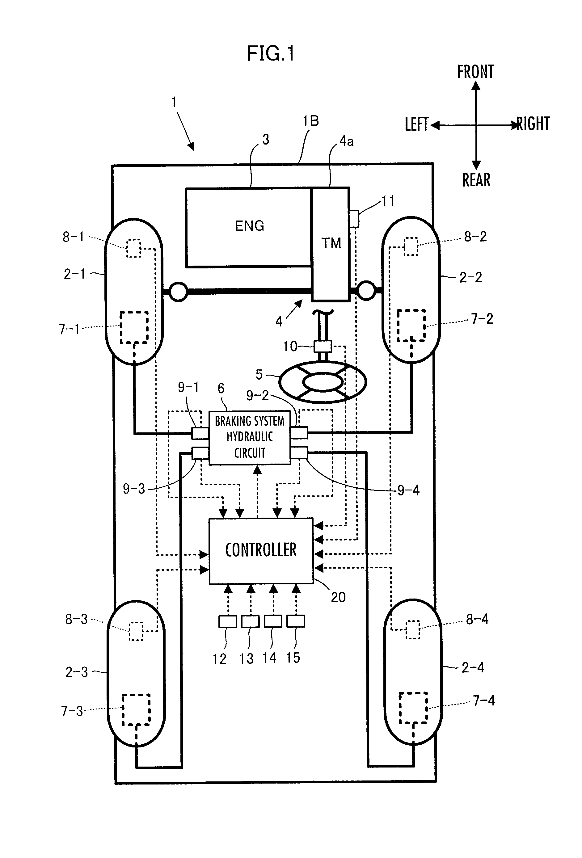
[0176]First, the processing by the controller 20 in a first embodiment will be described in detail. In the present embodiment, as illustrated by the block diagram of FIG. 3, the controller 20 has, as major functional means, an amount-to-be-observed detector 22, a vehicle model calculator 24, a μ estimator 26, a bank angle estimator 28, and a slope angle estimator 30.

[0177]The amount-to-be-observed detector 22 uses outputs from the aforesaid various sensors of the vehicle 1 (detection data) to carry out the processing for detecting predetermined types of amounts to be observed related to a behavior of the vehicle 1, and generates detected values of the amounts to be observed.

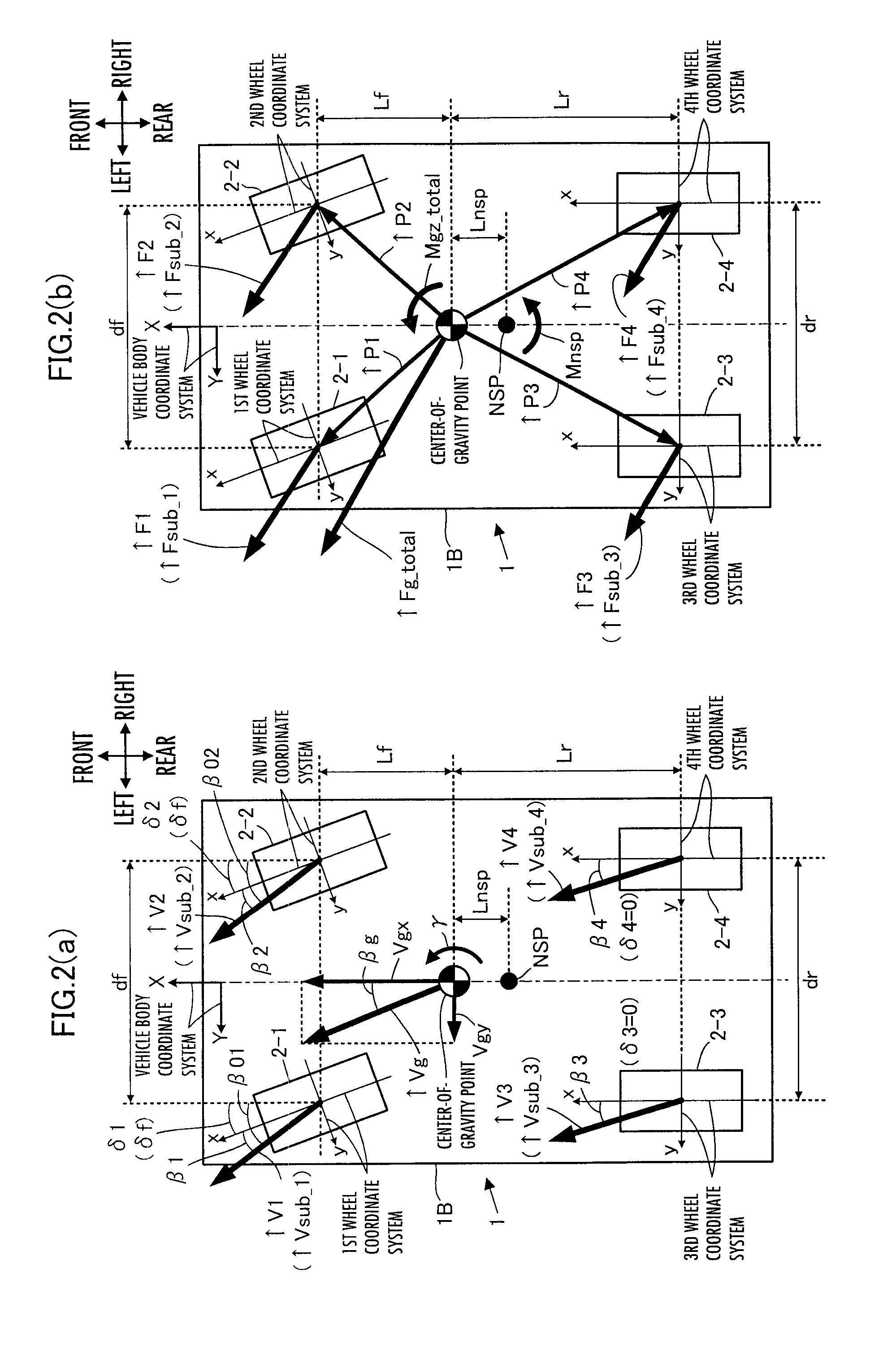
[0178]In the present embodiment, the amounts to be observed by the amount-to-be observed detector 22 include actual steering angles δ1_act and δ2_act of steering control wheels (front wheels) 2-1 and 2-2, an actual wheel speed Vw_i_act (i=1, 2, 3, 4), an actual yaw rate γ_act and an actual yaw angular acceleratio...

second embodiment

[0503]A second embodiment of the present invention will now be described with reference to FIG. 13.

[0504]The present embodiment differs from the aforesaid first embodiment only in the processing by the frictional coefficient increasing / decreasing manipulated variable determiner 26e of the μ estimator 26 (the processing in S122-5 of FIG. 12).

[0505]In this case, according to the present embodiment, the μ estimator 26 cancels updating the road surface frictional coefficient estimated value μ_estm according to the NSP yaw moment estimation error Mnsp_err in the case where a predetermined updating cancellation condition, which includes a condition related to the polarities of the NSP yaw moment detected value Mnsp_sens and the NSP yaw moment estimated value Mnsp_estm, applies. If the aforesaid updating cancellation condition does not hold, then the μ estimator 26 updates the road surface frictional coefficient estimated value μ_estm on the basis of Mnsp_err.

[0506]Here, Mnsp_sens and Mnsp...

third embodiment

[0527]A third embodiment of the present invention will now be described with reference to FIG. 14 and FIG. 15. The present embodiment differs from the aforesaid second embodiment only in the method for setting the gain adjustment parameter Kmu_att in a frictional coefficient increasing / decreasing manipulated variable determiner 26e.

[0528]In the second embodiment described above, Kmu_att has always been set to 1 in the case where the determination result of S122-5-1 is affirmative, i.e., the updating cancellation condition does not apply. In contrast thereto, according to the present embodiment, Kmu_att is set such that Kmu_att changes within a range from 0 to 1 according to Mnsp_estm and Mnsp_sens as illustrated in, for example, FIG. 14 in the case where the determination result in S122-5-1 is affirmative.

[0529]FIG. 14 visually illustrates the set values of Kmu_att corresponding to pairs of the values of Mnsp_estm and the values of Mnsp_sens on a coordinate plane, Mnsp_estm being o...


PUM


Abstract

A road surface frictional coefficient estimating apparatus has a device for determining a first estimated value of a yaw moment Mnsp_estm generated at an NSP of a vehicle due to the resultant force of road surface reaction forces acting on each wheel by using, for example, a frictional coefficient estimated value that has been determined, and a device for determining a second estimated value of a yaw moment Mnsp_sens generated at the NSP from the observed value of motional state amounts defining an inertial force moment at the NSP. The increasing / decreasing manipulated variable of the frictional coefficient estimated value is sequentially determined on an error (Mnsp_sens−Mnsp_estm) such that the error is converged to zero, and the road surface frictional coefficient is updated on the basis of the increasing / decreasing manipulated variable.

Description

BACKGROUND OF THE INVENTION[0001]1. Field of the Invention[0002]The present invention relates to a road surface frictional coefficient estimating apparatus which estimates the frictional coefficient of a road surface on which a vehicle is traveling.[0003]2. Description of the Related Art[0004]As the technique for estimating the frictional coefficient (hereinafter referred to simply as “μ” in some cases) of a road surface on which a vehicle is traveling, the techniques disclosed in, for example, Patent Publication No. 3669668 (hereinafter referred to as “patent document 1”) and Japanese Patent Application Laid-Open No. 2003-118554 (hereinafter referred to as “patent document 2”), have been proposed by the present applicant.[0005]According to the technique disclosed in patent document 1, a road surface reaction force acting on each wheel from a road surface (a cornering force (a lateral force of a vehicle) and a braking / driving force (a longitudinal force of the vehicle)) is estimated...

Claims


Application Information

Patent Timeline
Patent Type & Authority Patents(United States)
IPC IPC(8): G01M17/00B60W40/068
CPCB60T8/172B60W40/068B62D6/006B60T2210/12Y10T152/10792B60T2270/86
Inventor TAKENAKA, TORUURABE, HIROYUKIYANO, OSAMUMORI, YOSHIHIROUSHIMURA, TOMOYA
Owner HONDA MOTOR CO LTD
Why Eureka
Try Eureka