Field effect transistor gate process and structure
a field effect transistor and gate technology, applied in the field of field effect transistors and metalsemiconductor field effect transistors, can solve the problems of limiting the operation of the transistor or the reliability or both
- Summary
- Abstract
- Description
- Claims
- Application Information
AI Technical Summary
Problems solved by technology
Method used
Image
Examples
first embodiment
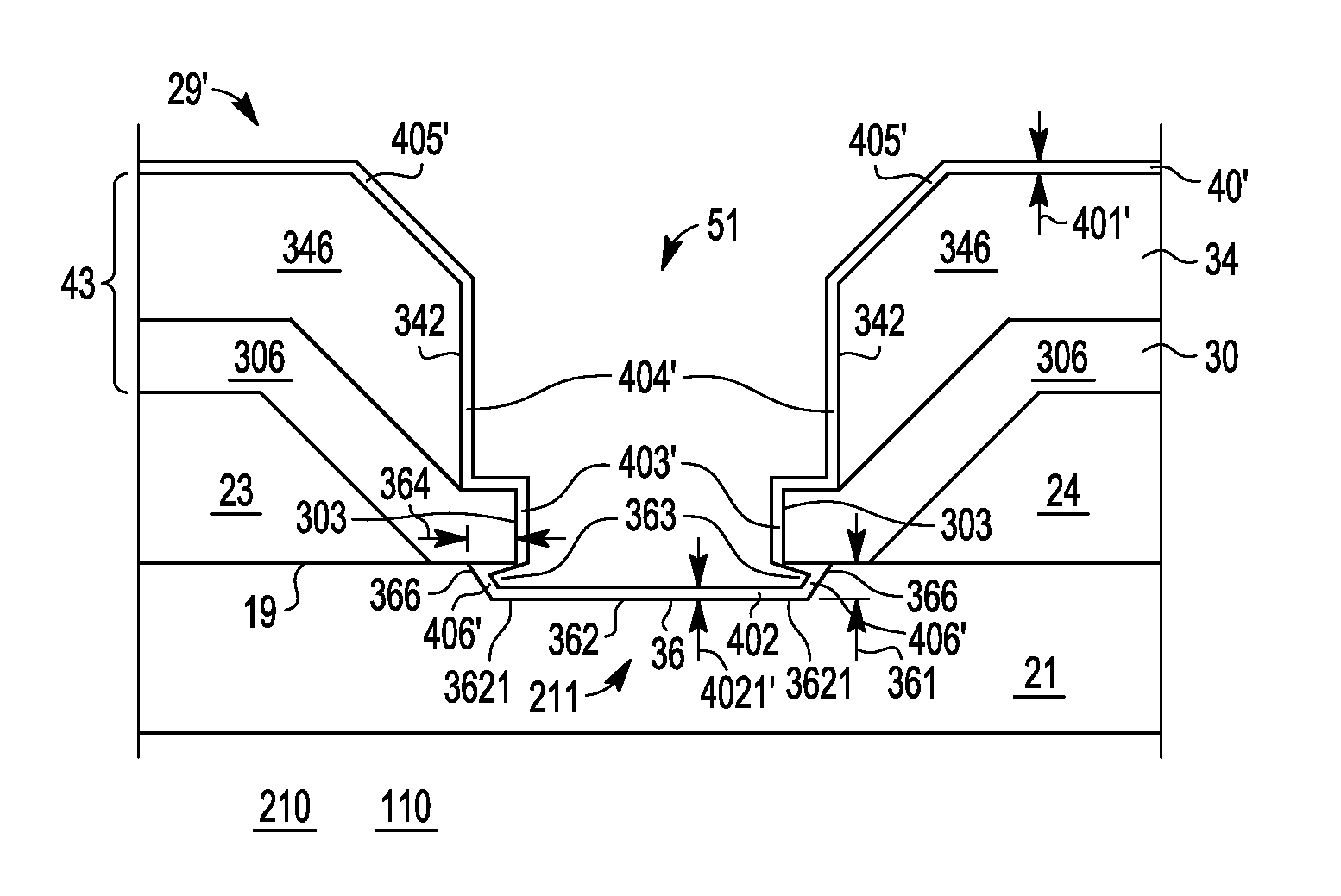
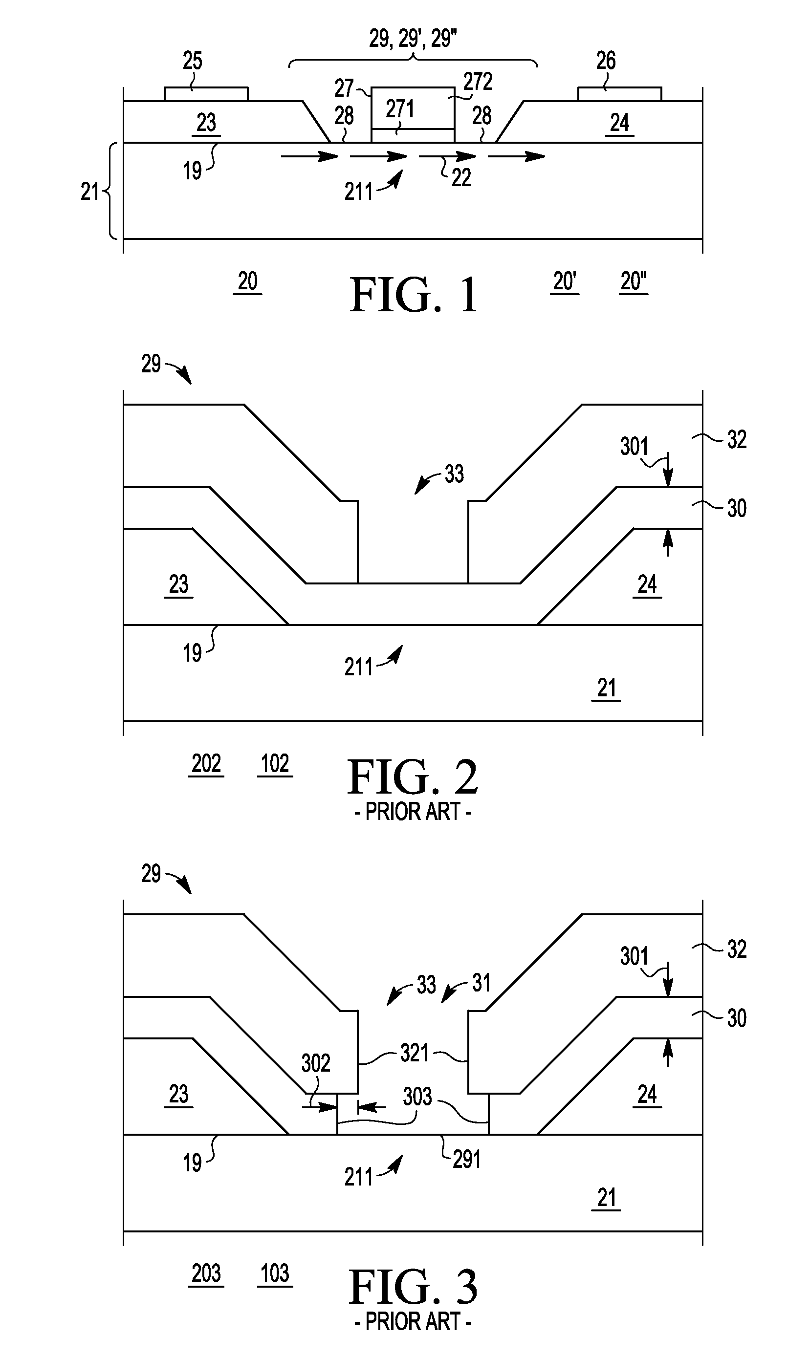
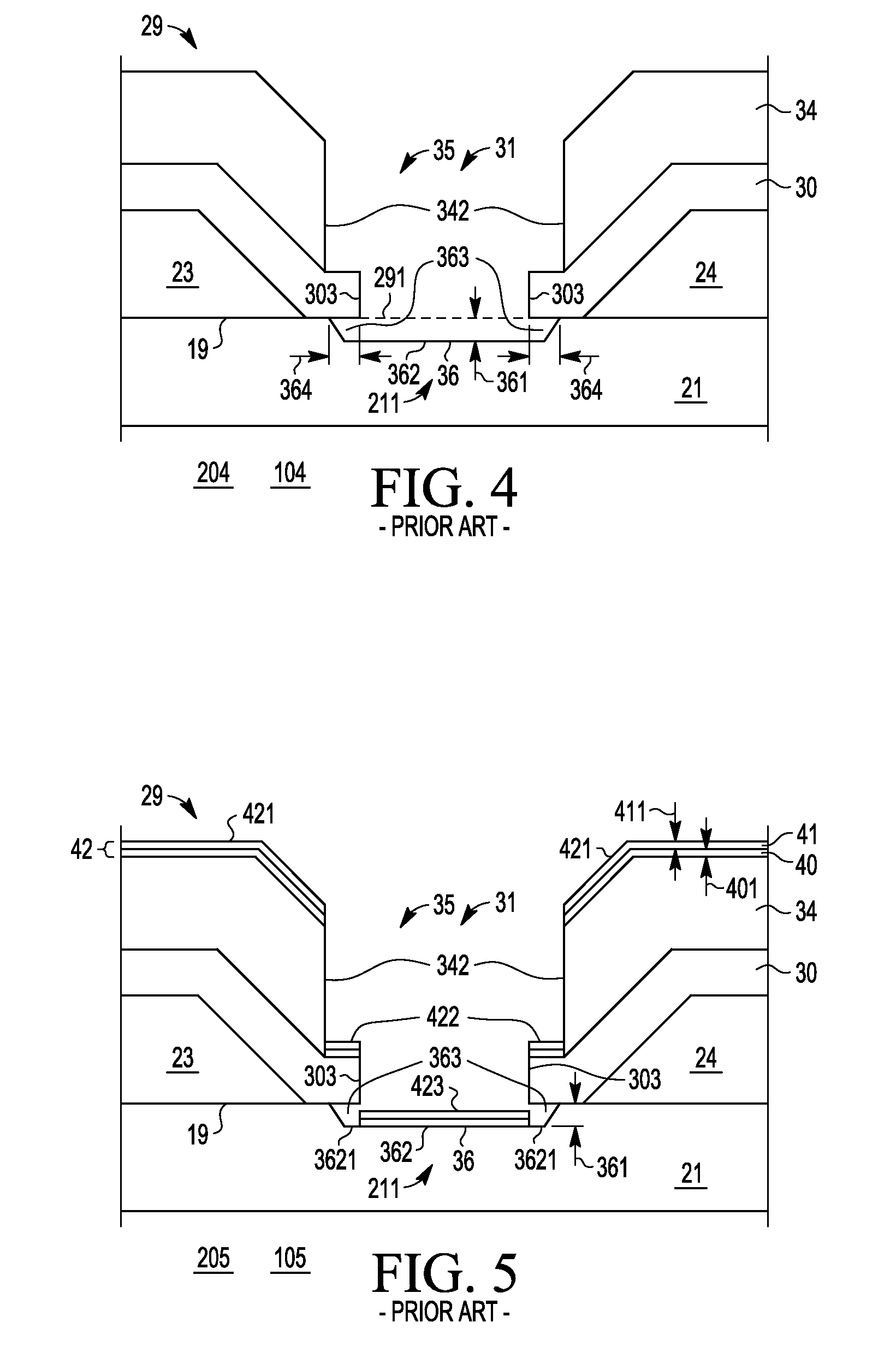
[0026] there is provided a method for forming a metal-semiconductor field effect transistor (MESFET) (20′, 20″), comprising, providing a substrate (21) having a mask layer (43) thereon with an opening (51) extending to a surface region (291) of the substrate (21), etching a gate recess (36) in the surface region (291) of the substrate (21) so as to expose a depressed surface (362) of the substrate (21) and also form surface undercut cavities (363) extending laterally under the mask layer (43) from the gate recess (36), and substantially conformally coating the depressed surface (362) and inner surfaces (366) of the surface undercut cavities (363) with a Schottky forming conductor (40′), thereby forming a Schottky gate contact (271) to the substrate (21), adapted when biased to control current flow in a channel (22) underlying the gate recess (36). According to a further embodiment, the method further comprises forming a conformal or non-conformal barrier layer conductor (41′, 41″) o...
second embodiment
[0027] there is provided a metal-semiconductor field effect transistor (MESFET) (20′, 20″), comprising, a semiconductor substrate (21) having a gate region (29′, 29″) in which is located a surface portion (362) of the substrate (21) bordered by lateral undercut regions (363), and a Schottky contact forming conductor (40′) overlying the surface portion (362) of the substrate (21) and on sidewalls (366) of the undercut regions (363). According to a still further embodiment, the undercut regions (363) have a first depth (361) substantially perpendicular to the surface portion (362) and the Schottky forming conductor (40′) has a first thickness (401′, 4021′) substantially perpendicular to the surface portion (362) and wherein the first thickness (401′, 4021′) is 30% to 80% of the first depth (361). According to a yet further embodiment, the substrate comprises a III-V material. According to a still yet further embodiment, the surface portion (362) is located in a recess (36) in the subs...
third embodiment
[0028] there is provided a method for forming a gate conductor (27) of a metal-semiconductor field effect transistor (MESFET), comprising, providing a substrate (21) having a semiconductor first surface (291), applying a mask (43) having an opening (51) above the semiconductor first surface (291), etching the semiconductor first surface (291) through the opening (51) substantially vertically to a first depth (361) thereby exposing an interior surface (362) of the substrate (21) and substantially laterally underneath edges (303) of the mask (43) adjacent the opening (51) to a first distance (364), thereby forming a recess (36) having the interior surface (362) and lateral undercut regions (363) with sidewalls (366, 3521) shadowed by the edges (303) of the mask (43), and conformally depositing a Schottky forming conductor (40′) of a first thickness (401′, 4021′) on the interior surface (362) and on the sidewalls (366, 3621) of the undercut regions (363). According to a further embodim...
PUM
 Abstract
Description
Claims
Application Information
 - R&D
- Intellectual Property
- Life Sciences
- Materials
- Tech Scout
- Unparalleled Data Quality
- Higher Quality Content
- 60% Fewer Hallucinations
Browse by: Latest US Patents, China's latest patents, Technical Efficacy Thesaurus, Application Domain, Technology Topic, Popular Technical Reports.
© 2025 PatSnap. All rights reserved.Legal|Privacy policy|Modern Slavery Act Transparency Statement|Sitemap|About US| Contact US: help@patsnap.com


