
Sound data decoding apparatus

a technology of sound data and decoding apparatus, which is applied in the direction of digital transmission, fluid pressure measurement, instruments, etc., can solve the problems of coded data being received, sound quality may degrade, and the proportion of sound data can be lost, so as to prevent the degradation of sound quality

Inactive Publication Date: 2012-12-04
NEC CORP
View PDF20 Cites 0 Cited by
  • Summary
  • Abstract
  • Description
  • Claims
  • Application Information

AI Technical Summary

Benefits of technology

[0011]According to the present invention, an error in a sound data is compensated while preventing a degradation of sound quality.

Problems solved by technology

When a sound data coded based on such a compression method is transmitted, in some case, a portion of the sound data can be lost due to an error relevant to radio communication or due to congestion of the network.
In such error compensation, sound quality may degrade.
The problem may occur in case that correct coded data is received after the loss of coded data.

Method used


Image

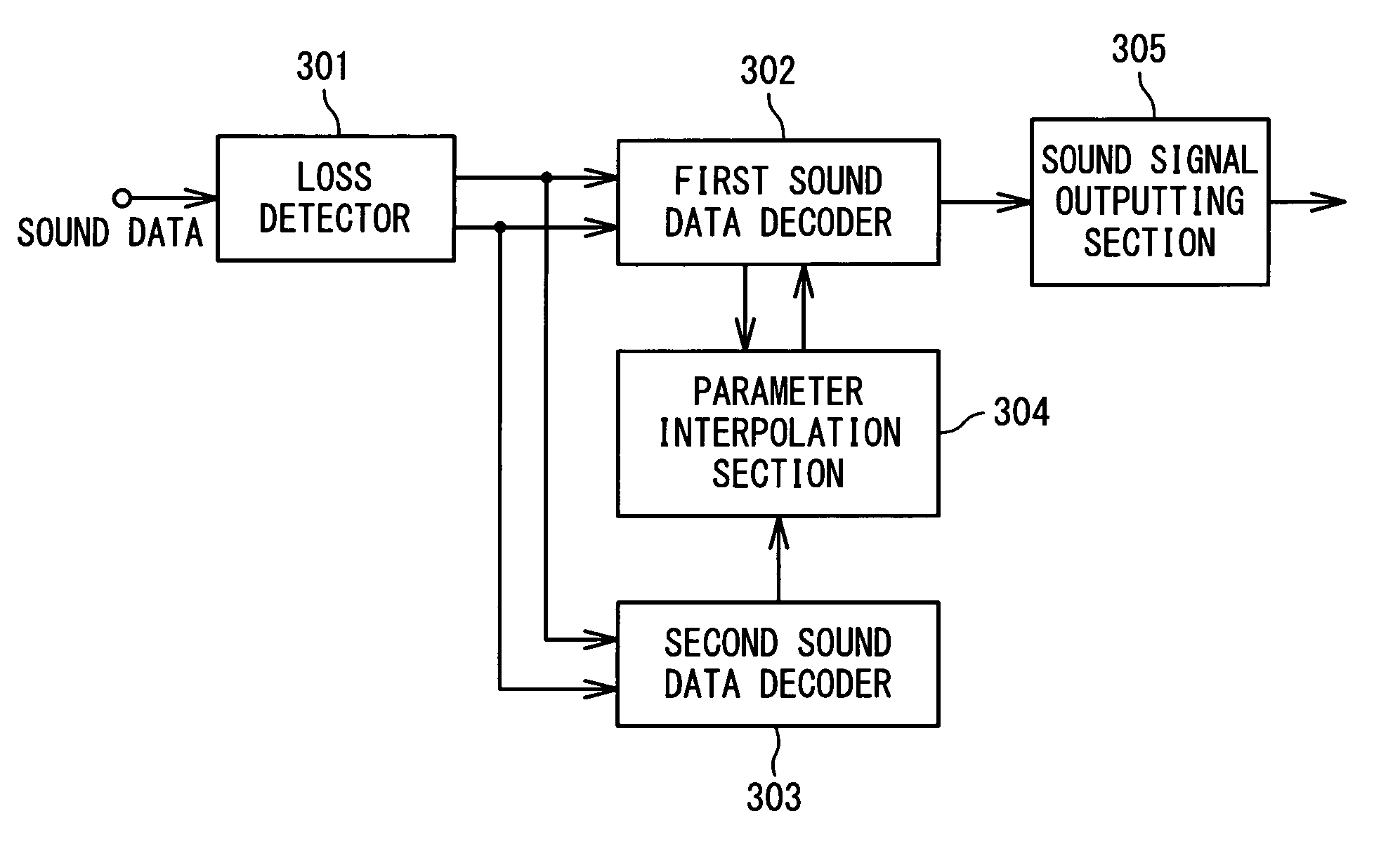
  • Sound data decoding apparatus
  • Sound data decoding apparatus
  • Sound data decoding apparatus

Examples


Embodiment Construction

[0022]Exemplary embodiments of the present invention will be described with reference to the attached drawings. The present invention is not limited to the exemplary embodiments.

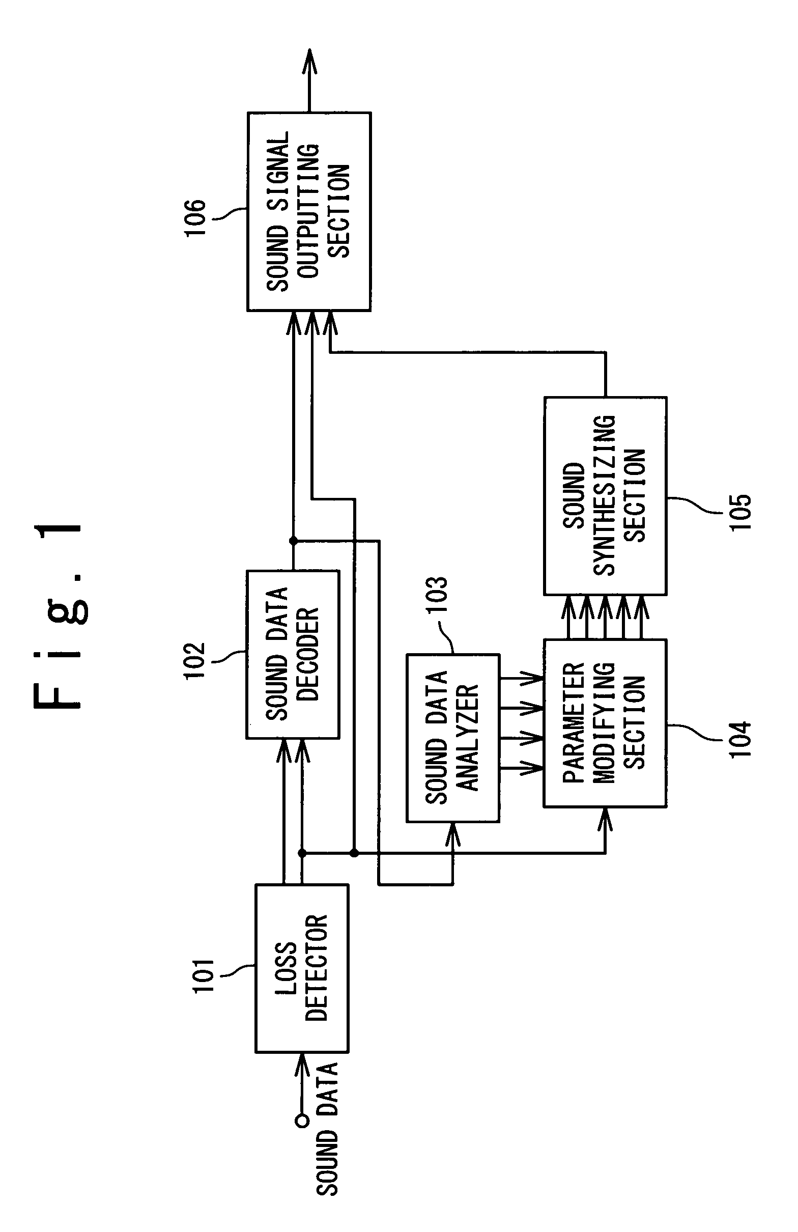
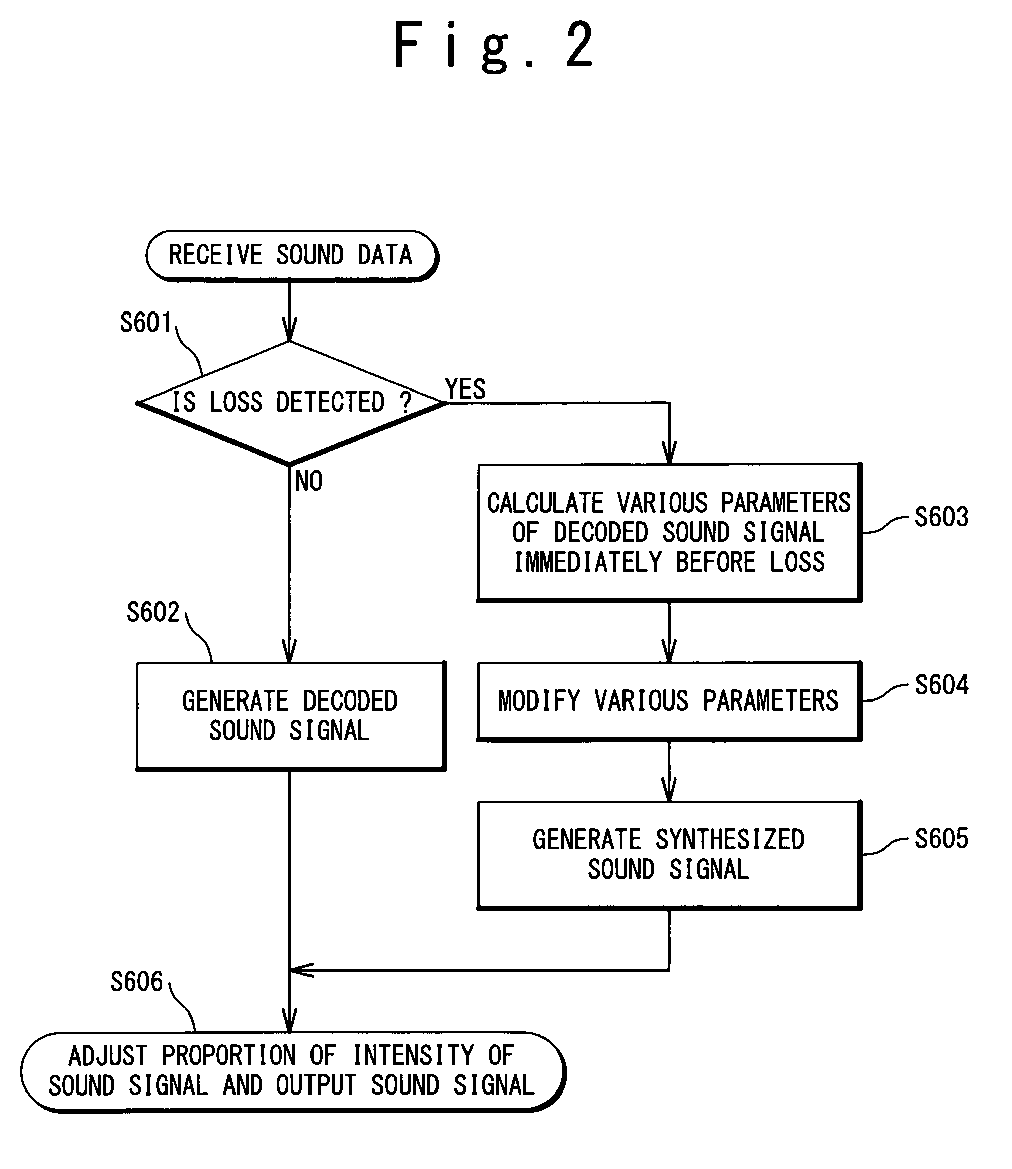
[0023]A first exemplary embodiment of the present invention will be described below with reference to FIGS. 1 and 2.

[0024]FIG. 1 shows a configuration of a sound data decoding apparatus for sound data coded based on a waveform coding method such as the G.711 method. The sound data decoding apparatus according to the first exemplary embodiment includes a loss detector 101, sound data decoder 102, sound data analyzer 103, parameter modifying section 104, sound synthesizing section 105 and sound signal outputting section 106. The sound data means a data which is generated through coding a series of sound, and means a data of sound, in which at least one sound frame is included.

[0025]The loss detector 101 outputs a received sound data to the sound data decoder 102. The loss detector 101 detects whether a loss ex...


PUM

PropertyMeasurementUnit
lengthaaaaaaaaaa
residual signal gainaaaaaaaaaa
timeaaaaaaaaaa

Abstract

A sound data decoding apparatus based on a waveform coding method includes a loss detector, sound data decoder, sound data analyzer, parameter modifying section and sound synthesizing section. The loss detector detects whether a loss exists in a sound data. The sound data decoder decodes the sound data to generate a first decoded sound signal. The sound data analyzer extracts a first parameter from the first decoded sound signal. The parameter modifying section modifies the first parameter based on a result of the detection of loss. The sound synthesizing section generates a first synthesized sound signal by using the modified first parameter. Thus, a deterioration of sound quality is prevented in the error compensation of sound data.

Description

[0001]This application is the National Phase of PCT / JP2007 / 064421, filed Jul. 23, 2007, which claims priority to Japanese Application No. 2006-204781, filed Jul. 27, 2006, the disclosures of which are hereby incorporated by reference in their entirety.TECHNICAL FIELD[0002]The present invention relates to a sound data decoding apparatus, sound data converting apparatus, and error compensating method.BACKGROUND ART[0003]In a transmission of a sound data through a circuit switching network or packet network, a coding and decoding are executed to transmit and to receive a sound signal. As a sound compression method, for example, an ITU-T (International Telecommunication Union Telecommunication Standardization Sector) recommendation G.711 method and a CELP (Code-Excited Linear Prediction) method have been known.[0004]When a sound data coded based on such a compression method is transmitted, in some case, a portion of the sound data can be lost due to an error relevant to radio communicat...

Claims


Application Information

Patent Timeline
Patent Type & Authority Patents(United States)
IPC IPC(8): G01L19/14G10L19/005G10L19/18
CPCG10L19/005G10L19/06G10L19/12
Inventor ITO, HIRONORIOZAWA, KAZUNORI
Owner NEC CORP
Learn More