Axial flow fan

a technology of axial flow fans and rotors, which is applied in the direction of computer aided design, special data processing applications, and liquid fuel engine components, etc., can solve the problems of reducing the operational efficiency of the fan and the rotor, generating a considerable amount of noise and turbulence, and relatively inefficient fans and rotors

Active Publication Date: 2012-12-11
PAX SCI +1
View PDF160 Cites 9 Cited by
  • Summary
  • Abstract
  • Description
  • Claims
  • Application Information

AI Technical Summary

Problems solved by technology

As a result, fans and rotors remain relatively inefficient.
A part of this inefficiency is the result of fans and rotors generating a considerable amount of noise and turbulence.
Similarly, fans and rotors used in liquid environments typically result in cavitation.
Noise, turbulence, and cavitation reduce the operational efficiency of the fan and rotor.
Much of the noise, turbulence, and unwanted torque in prior art fan design may be attributable to the surface design of the fan or rotor.
These pre-existing designs are not necessarily designed or intended for that particular operating environment.
Determining which pre-existing design is adequate or ‘good enough’ for a particular environment is a never-ending exercise.
Notwithstanding these adequate results, some degree of the aforementioned noise, turbulence, and / or unwanted torque will inevitably remain.

Method used


Image

  • Axial flow fan
  • Axial flow fan
  • Axial flow fan

Examples


Embodiment Construction

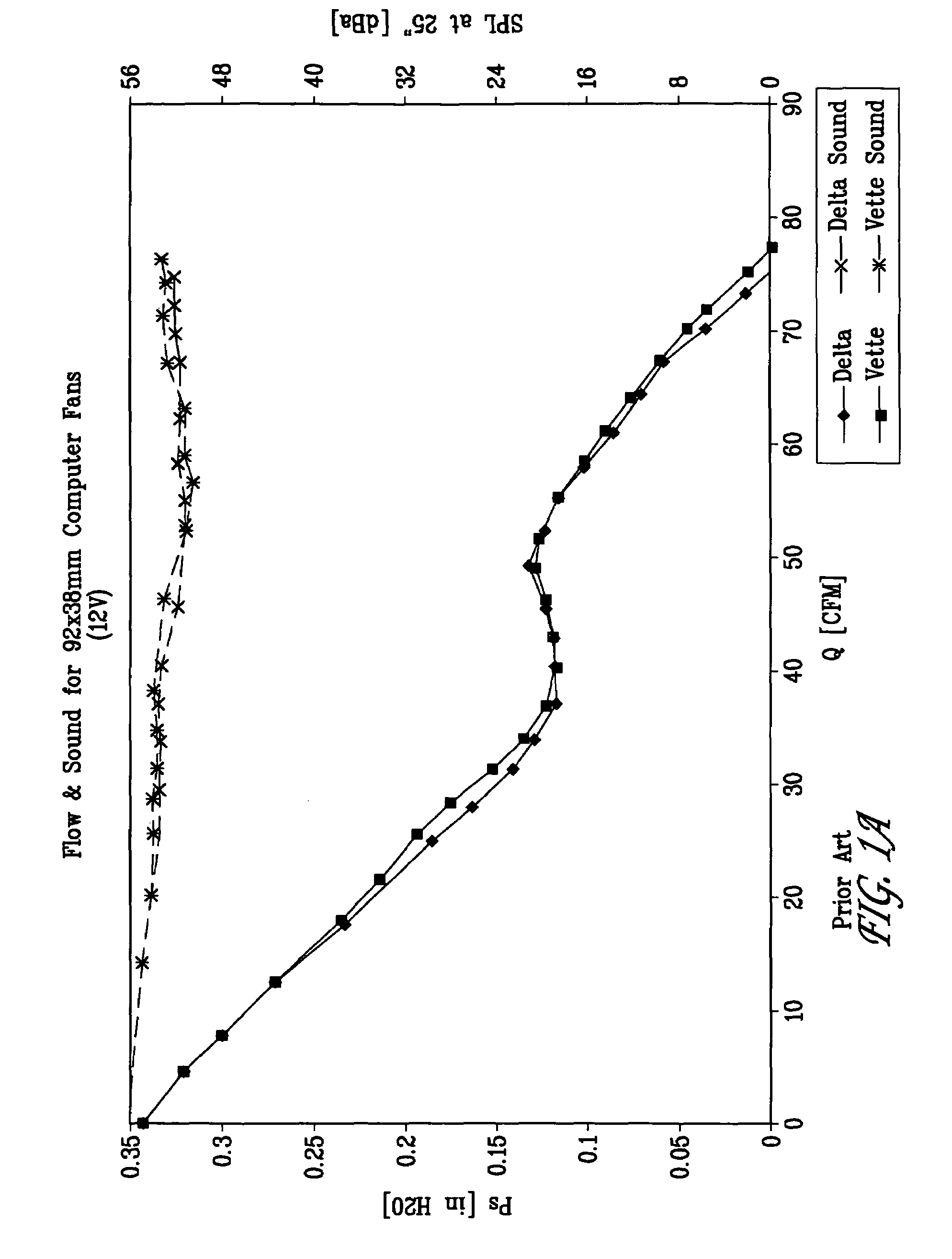
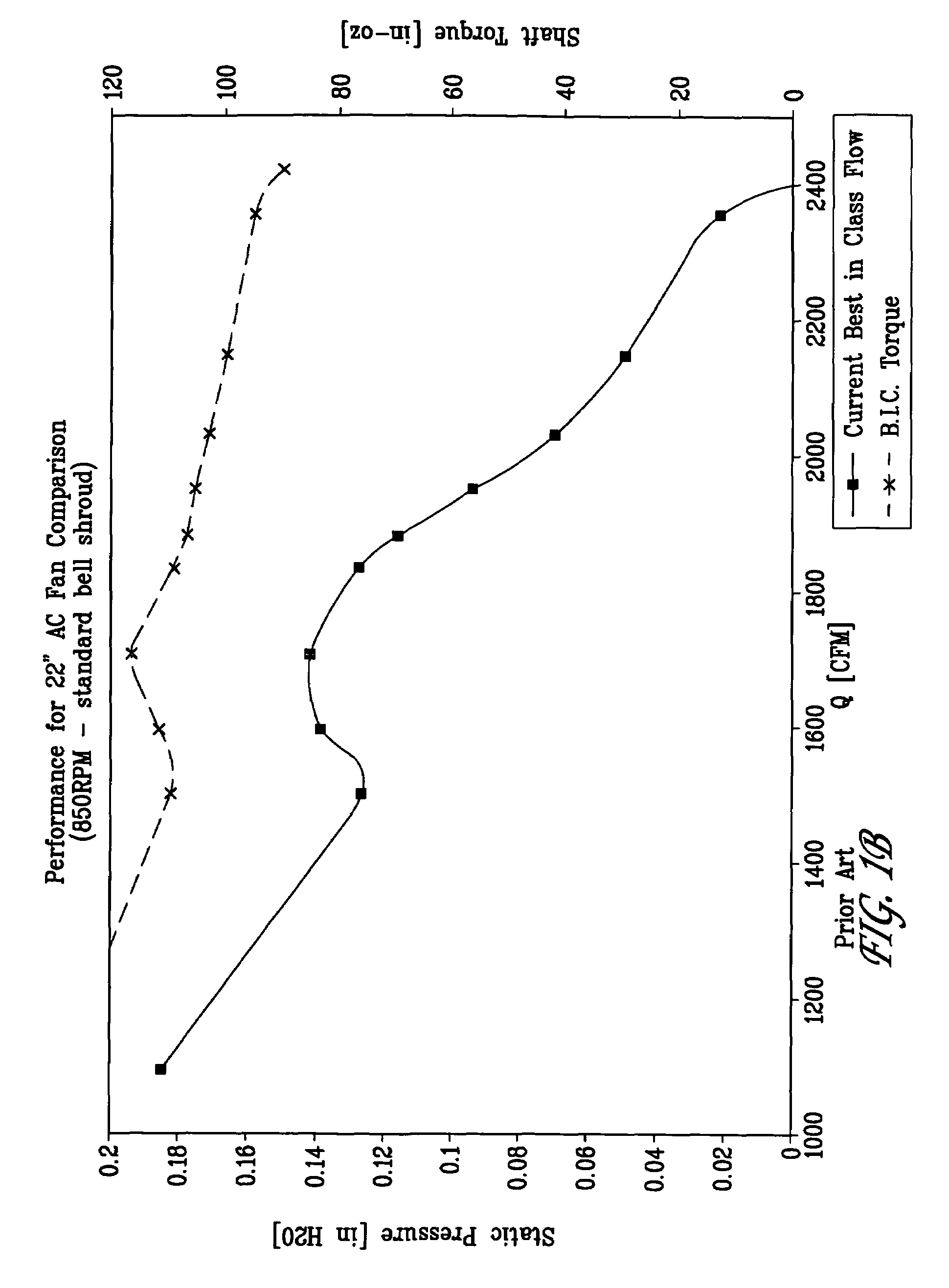
[0028]Embodiments of the present invention provide for a fan that is quieter for the same or better output throughout a range of operating points compared to prior art fan designs. FIG. 2A is a chart exhibiting flow and sound efficiency of an exemplary fan as may be designed in accordance with the present invention compared to the inefficiencies of a prior art fan like that found in FIG. 1A. FIG. 2B, in turn, is a chart exhibiting flow and torque efficiency of an exemplary surface profile as may be designed for a fan in accordance with the present invention compared to the inefficiencies of a prior art fan like that found in FIG. 1B.

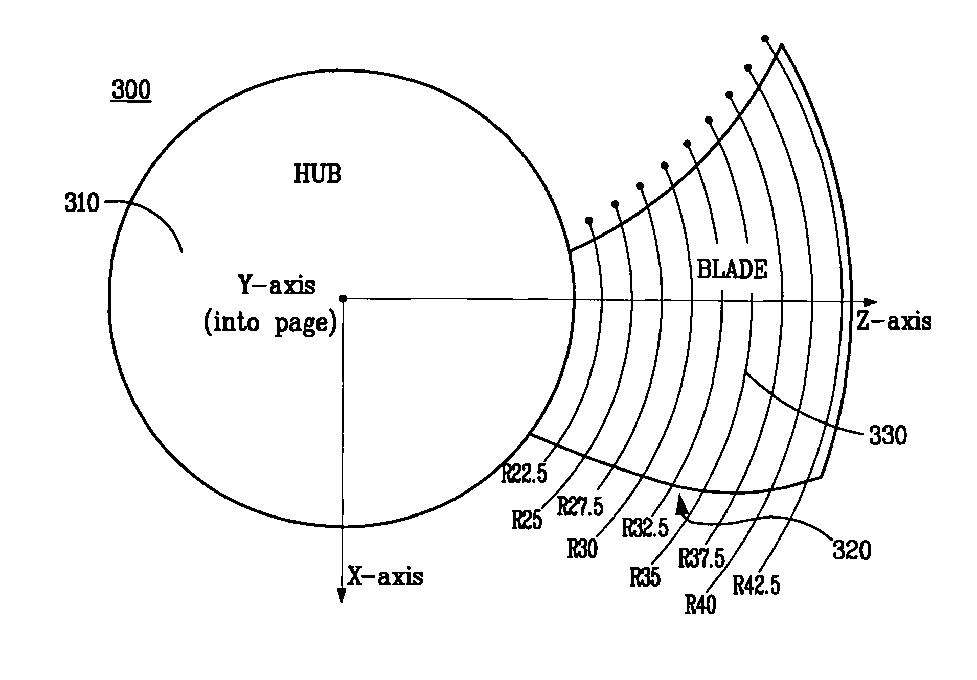
[0029]FIG. 3 illustrates a portion of an exemplary fan 300 and surface profile 330 according to an embodiment of the present invention. Fan 300 may be motor driven or subject to the natural flow of a fluid (e.g., liquid or gas). Fan 300 includes a hub 310, which may be approximately cylindrical or conical in shape. Hub 310 may be hollowed like that of FI...


PUM

PropertyMeasurementUnit
diameteraaaaaaaaaa
radiusaaaaaaaaaa
dimensionaaaaaaaaaa

Abstract

A fan or rotor design where the surface profile may be configured to desired dimensions particular to a given operating environment is disclosed.

Description

CROSS-REFERENCE TO RELATED APPLICATIONS[0001]The present application claims the priority benefit of U.S. provisional patent application No. 60 / 827,677 filed Sep. 29, 2006 and entitled “Axial Flow Fan” and U.S. provisional patent application No. 60 / 950,610 filed Jul. 19, 2007 and entitled “Surface Profile for a Quiet Rotor or Stator.” The disclosure of these commonly owned applications are incorporated herein by reference.[0002]This application is related to U.S. Pat. No. 5,934,877 for a “Rotor with Logarithmic Scaled Shape” and U.S. Pat. No. 6,702,552 for an “Impeller Having Blade(s) Conforming to the Golden Section of a Logarithmic Curve.” The disclosures of these commonly owned patents are incorporated herein by reference.BACKGROUND OF THE INVENTION[0003]1. Field of the Invention[0004]The present invention generally concerns axial flow fans and rotors. More specifically, the present invention concerns a surface profile for axial flow fans and rotors used in environments requiring ...

Claims


Application Information

Patent Timeline
Patent Type & Authority Patents(United States)
IPC IPC(8): F03B3/12
CPCF04D29/384G06F17/5009Y10T29/49327Y10T29/49321G06F2217/16G06F30/20G06F2111/10
Inventor HARMAN, JAYDEN DAVIDPENNEY, KIMBERLYLEES, PAULKOELMAN, ONNO
Owner PAX SCI
Why Eureka
Try Eureka