Shroud plate with lighting system

a technology of lighting system and shield plate, which is applied in the direction of lighting and heating apparatus, cell components, lighting support devices, etc., can solve the problems of endangering the wearer's descent with a parachute, and the wearer's head jerking,

Active Publication Date: 2012-12-25
NOROTOS
View PDF13 Cites 50 Cited by
  • Summary
  • Abstract
  • Description
  • Claims
  • Application Information

AI Technical Summary

Problems solved by technology

Although previous mounts exist that allow for a hands-free configuration, such mounts may have edges, corners or other configurations that may snag on certain objects, such as a shroud line of a parachute or a tree branch, and thereby cause a wearer's head to jerk in an undesired direction and with a large force, or in the case of a shroud line, cut the line entirely and thereby endanger a wearer descending with a parachute.

Method used


Image

  • Shroud plate with lighting system
  • Shroud plate with lighting system
  • Shroud plate with lighting system

Examples


Embodiment Construction

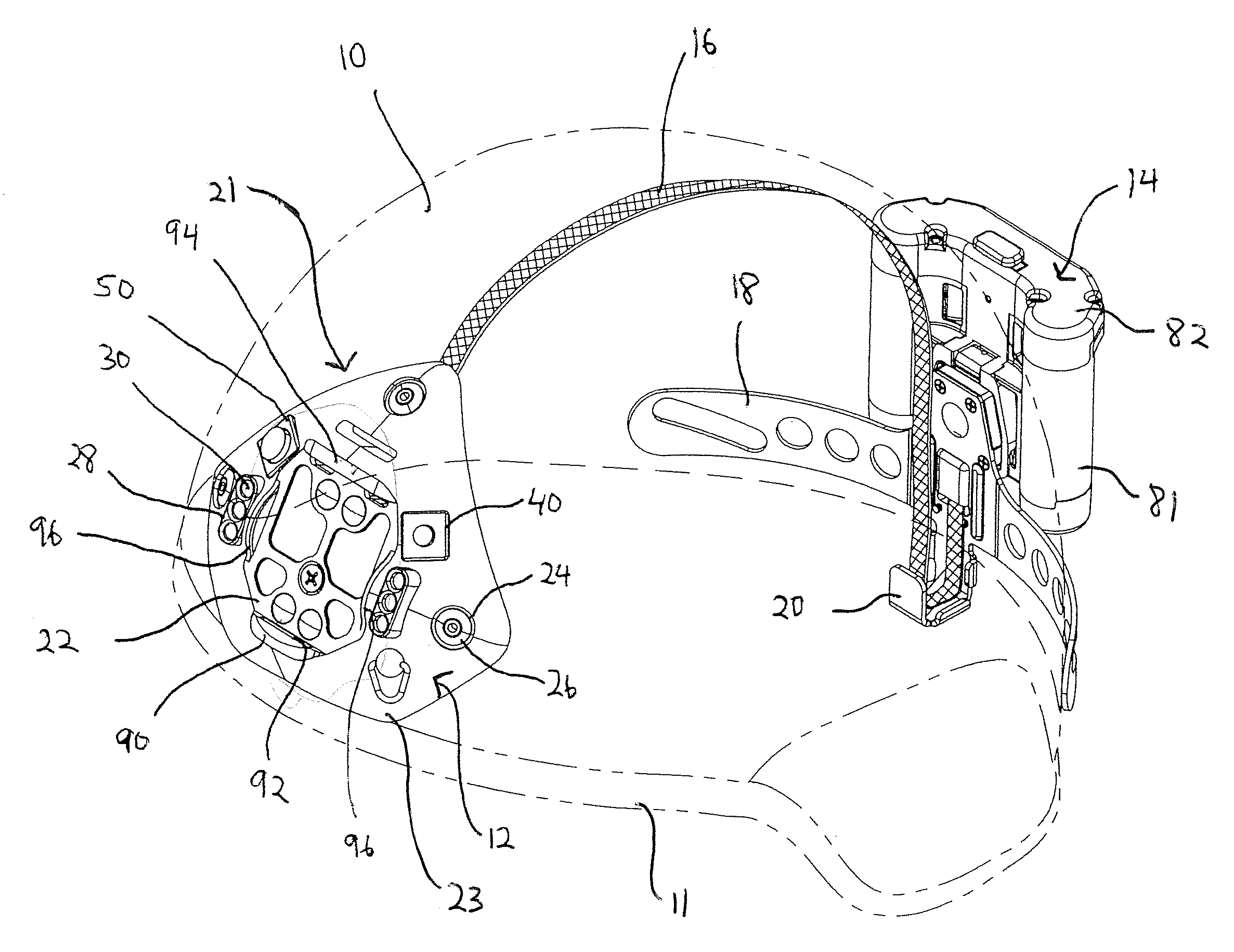
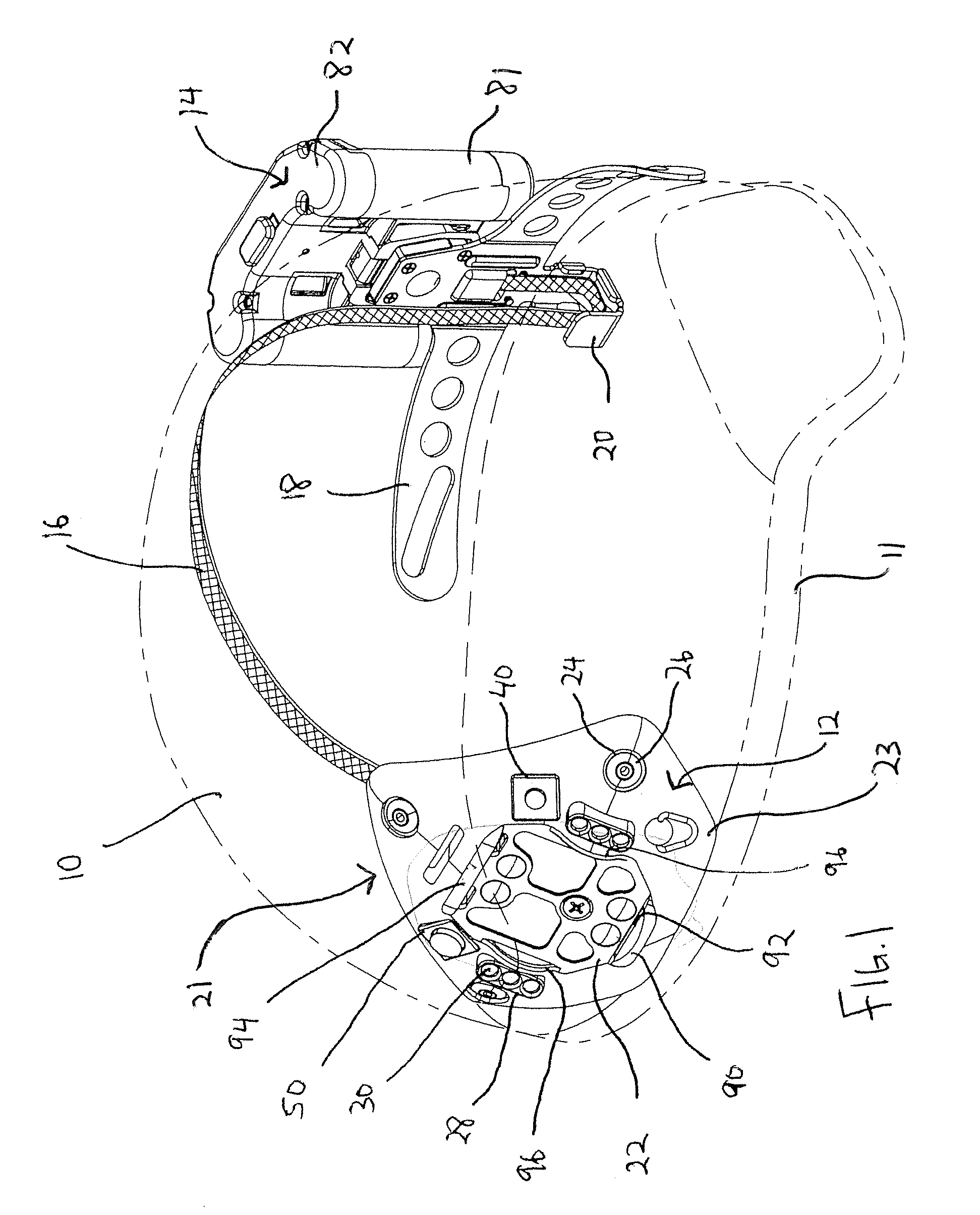
[0020]Embodiments of the present invention are directed to a shroud plate for attaching night vision goggles to headgear, such as a helmet, the shroud plate having a lighting system to provide a user with a hands-free, adjustable light to be used instead of or simultaneously with night vision goggles. As described in more detail below, the shroud plate with the lighting system has a relatively low profile that generally matches a contour of a user's headgear so that the shroud plate does not have any edges on which another object, such as a shroud line of a parachute or a tree branch, can easily snag and force the headgear in a direction that may injure the wearer.

[0021]With reference to FIG. 1, in one embodiment, a shroud plate 12 is attached to headgear 10 in the form of a helmet. The shroud plate may be similar to the shroud plates described in U.S. Pat. No. 6,751,810, filed Mar. 13, 2003, the entire disclosure of which is incorporated herein by reference. However, it will be app...


PUM


Abstract

A light for headgear includes a shroud plate having a shell configured to receive a goggle mount, the shell having a periphery generally conforming to a contour of the headgear; and a lighting system on the shell having at least one light. The light further includes a power unit electrically coupled to the lighting system.

Description

CROSS-REFERENCE TO RELATED APPLICATION[0001]This application claims the benefit of U.S. Provisional Application No. 61 / 173,964, filed Apr. 29, 2009, in the U.S. Patent and Trademark Office, the entire disclosure of which is incorporated herein by reference.BACKGROUND[0002]Night vision goggles are commonly used by military personnel for conducting operations in low light or night conditions. Assemblies for mounting night vision goggles to a helmet or other headgear are well known in the art. These mounting assemblies allow a user's hands to remain free while viewing a scene through the night vision goggles.[0003]Although previous mounts exist that allow for a hands-free configuration, such mounts may have edges, corners or other configurations that may snag on certain objects, such as a shroud line of a parachute or a tree branch, and thereby cause a wearer's head to jerk in an undesired direction and with a large force, or in the case of a shroud line, cut the line entirely and ther...

Claims


Application Information

Patent Timeline
Patent Type & Authority Patents(United States)
IPC IPC(8): F21V21/084
CPCA42B3/04A42B3/044F21V21/084F41H1/04H01M2/1055F41G1/35H01M50/213Y02E60/10
Inventor SOTO, RONALD R.PRENDERGAST, JONATHON R.PATTON, III, CHARLES ROYSTON
Owner NOROTOS
Why Eureka
Try Eureka