Minimal access occipital plate

a technology of occipital bone plate and small access, which is applied in the field of cervical spine apparatus and methods, can solve the problems of requiring a significant amount of force to penetrate the dense cortical bone, affecting the treatment effect, and affecting the quality of life of patients,

Inactive Publication Date: 2013-01-08
AESCULAP IMPLANT SYST
View PDF35 Cites 12 Cited by
  • Summary
  • Abstract
  • Description
  • Claims
  • Application Information

AI Technical Summary

Problems solved by technology

Drilling and tapping holes at the rear of the skull is a difficult procedure that requires a significant amount of force to penetrate the dense cortical bone.
The process is further complicated by the angle of approach that is required for instruments.
Because the plate is positioned in close proximity to the back of the neck, the working area around the plate location is extremely confined.
Large incisions are clearly undesirable because they are invasive, introduce greater risk of complications, and require long recovery times. Moreover, longer incisions are not always effective in providing sufficient clearance for instruments.
Cervical deformities that obstruct the area around the occiput bone, for example, can make it impossible to position instrument shafts at the proper angle necessary to access the screws.

Method used


Image

  • Minimal access occipital plate
  • Minimal access occipital plate
  • Minimal access occipital plate

Examples


Embodiment Construction

[0018]Although the invention is illustrated and described herein with reference to specific embodiments, the invention is not intended to be limited to the details shown. Rather, various modifications may be made in the details within the scope and range of equivalents of the claims and without departing from the invention.

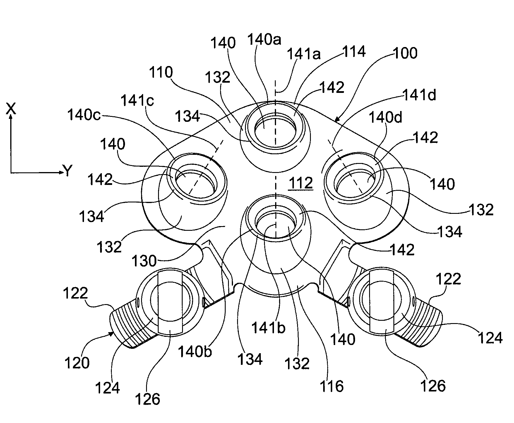
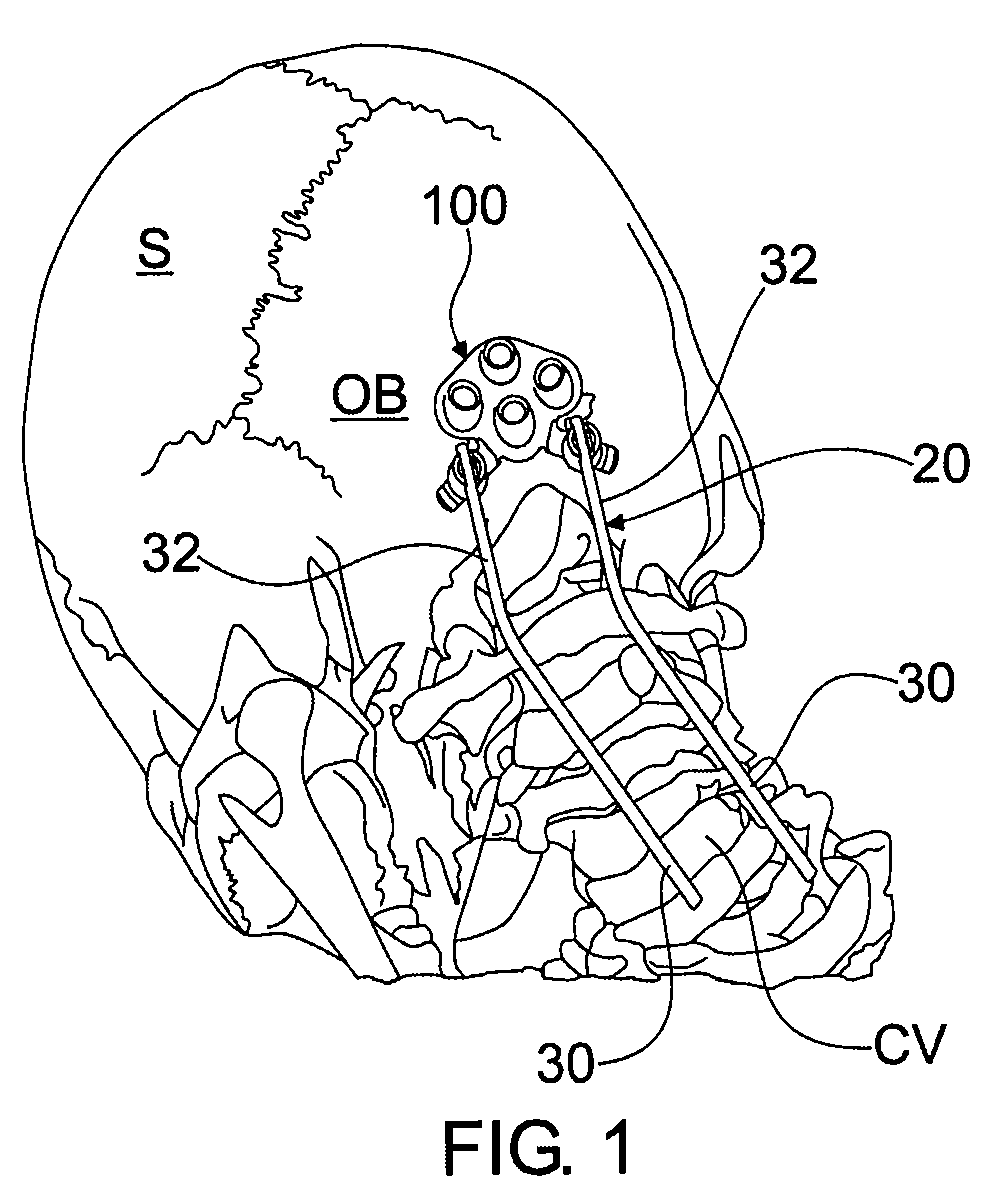
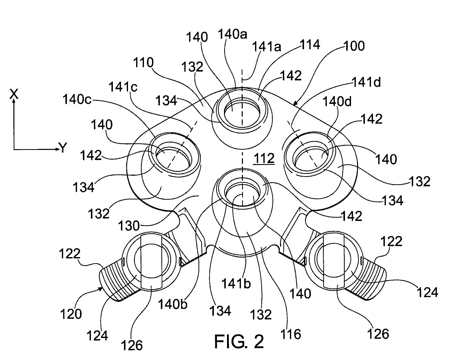
[0019]Occipital bone plates in accordance with the present invention provide a mechanism for stabilizing the base of the skull and cervical spine, while allowing surgical instrumentation to be held away from the cervical spine. In addition, bone plates in accordance with the invention provide a mechanism that reduces the size of incisions. Moreover, bone plates in accordance with the invention provide a stronger engagement between the occiput bone and bone screws. These combined benefits are achieved by selective angulation of screw holes in the bone plate. By angulating screw holes with respect to a reference plane, such as the plate's base portion, the screw hol...


PUM


Abstract

A bone plate for securing a spinal fixation element to bone includes a base portion having a top face, a rod receiving portion and a bone anchor receiving portion. The bone anchor receiving portion includes a plurality of angled holes for receiving bone screws. At least one of the screw holes is oriented at an acute angle relative to the top face of the plate.

Description

FIELD OF THE INVENTION[0001]The present invention relates generally to apparatuses and methods for treating the cervical spine, and more particularly to an occipital bone plate that can be used when access and work space around the occiput bone are limited.BACKGROUND OF THE INVENTION[0002]Occipitocervical fixation may be accomplished by using a bone plate attached to the occiput bone on the posterior of the skull, in conjunction with spinal rods. In many cases, the bone plate is attached to the skull with bone screws. Drilling and tapping holes at the rear of the skull is a difficult procedure that requires a significant amount of force to penetrate the dense cortical bone. The process is further complicated by the angle of approach that is required for instruments. Because the plate is positioned in close proximity to the back of the neck, the working area around the plate location is extremely confined. Moreover, the orientation of the plate is such that the plate extends more or ...

Claims


Application Information

Patent Timeline
Patent Type & Authority Patents(United States)
IPC IPC(8): A61B17/80
CPCA61B17/7055
Inventor CHEEMA, NAVEEDAPFELBAUM, RONGEISLER, FREDKHOO, LARRY
Owner AESCULAP IMPLANT SYST
Why Eureka
Try Eureka