
Intervertebral implant with blades for connecting to adjacent vertebral bodies

a technology of intervertebral implants and adjacent vertebrae, applied in the field of implants, can solve problems such as suboptimal surgical exposur

Active Publication Date: 2013-02-26
DEPUY SYNTHES PROD INC
View PDF6 Cites 35 Cited by
  • Summary
  • Abstract
  • Description
  • Claims
  • Application Information

AI Technical Summary

Benefits of technology

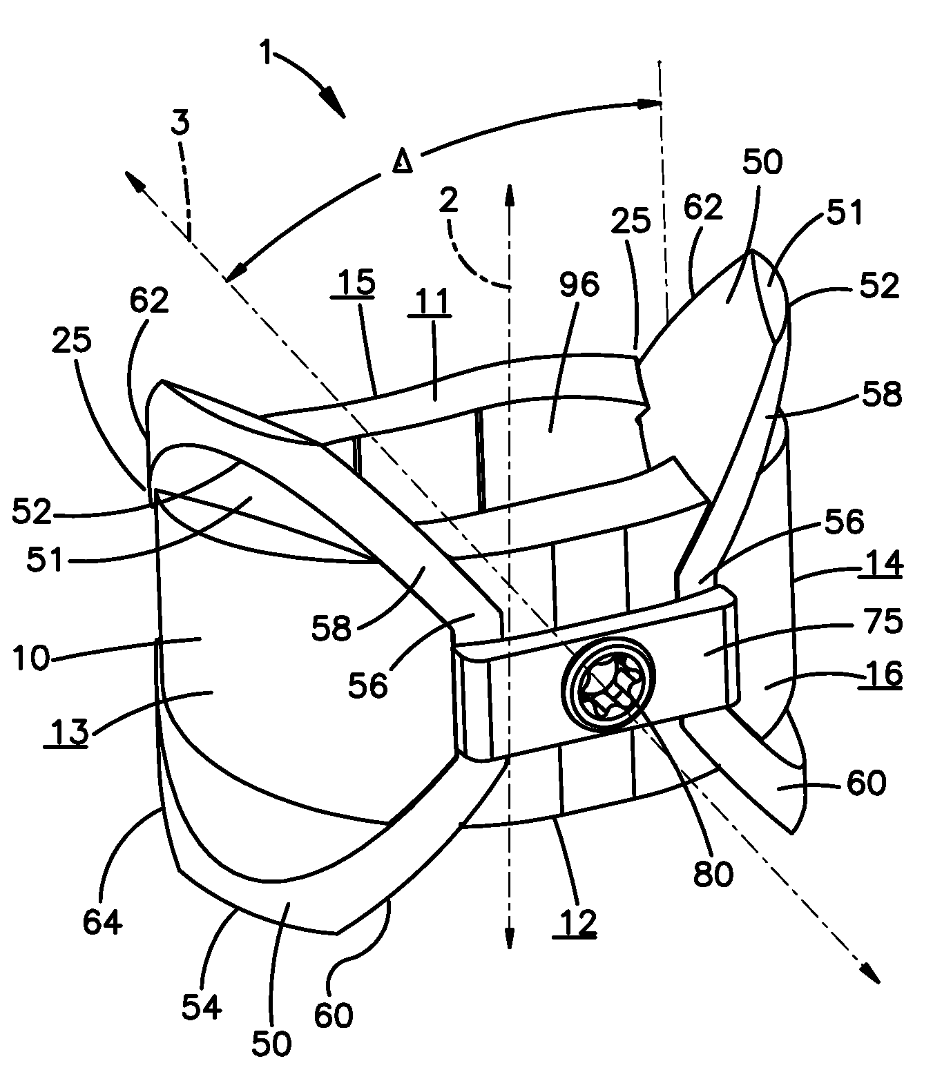
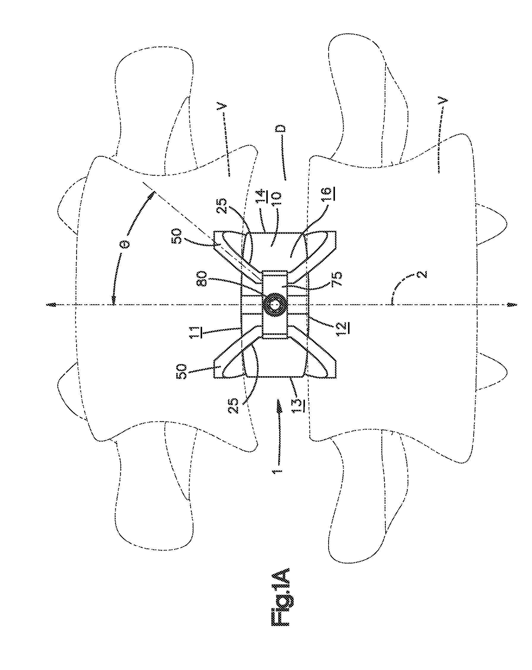
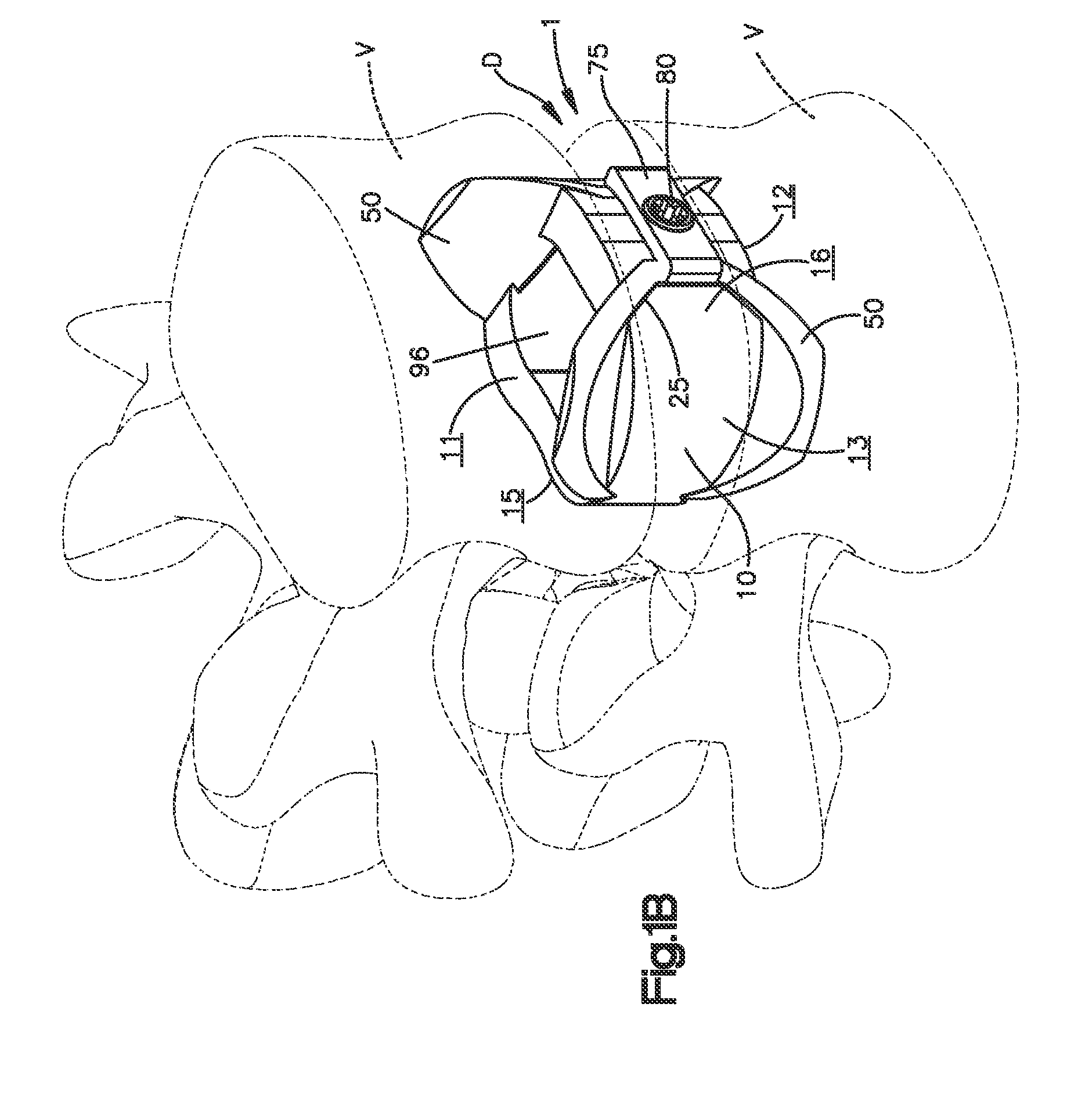
The present invention relates to an intervertebral implant for replacing a damaged spine disc. The implant has a spacer portion and blade elements that secure it to adjacent vertebral bodies. The implant can be inserted using a direct lateral trans-psoas approach without supplemental rigid fixation. The blade elements are integrally formed with the plate portion or formed as separate elements that are insertable into channels on the plate portion. The method includes drilling boreholes into the adjacent vertebral bodies and inserting the blade element into the channels on the plate portion. The technical effects of the invention include improved spine stability, reduced pain, and improved mobility.

Problems solved by technology

However, each of the bone screws is typically fastened at a different angle, which can create a situation of suboptimal surgical exposure.

Method used


Image

  • Intervertebral implant with blades for connecting to adjacent vertebral bodies
  • Intervertebral implant with blades for connecting to adjacent vertebral bodies
  • Intervertebral implant with blades for connecting to adjacent vertebral bodies

Examples


Embodiment Construction

[0041]Certain terminology is used in the following description for convenience only and is not limiting. The words “right”, “left”, “lower”, “upper”, “top”, and “bottom” designate directions in the drawings to which reference is made. The words “inwardly” or “distally” and “outwardly” or “proximally” refer to directions toward and away from, respectively, the geometric center of the intervertebral implant, spacer, blade elements and related parts thereof. The words, “anterior”, “posterior”, “superior”, “inferior” and related words and / or phrases designate preferred positions and orientations in the human body to which reference is made and are not meant to be limiting. The terminology includes the above-listed words, derivatives thereof and words of similar import.

[0042]Similar reference numerals will be utilized throughout the application to describe similar or the same components of each of the preferred embodiments of the intervertebral implant described herein and the descriptio...


PUM

PropertyMeasurementUnit
blade angleaaaaaaaaaa
angleaaaaaaaaaa

Abstract

An intervertebral implant (300) for insertion into an intervertebral disc space between adjacent vertebral bodies or between two bone portions. The implant includes a spacer portion (310), a plate portion (330) operatively coupled to the spacer portion and one or more blades (350) for securing the implant to the adjacent vertebral bodies. The blades preferably include superior and inferior cylindrical pins (360) for engaging the adjacent vertebral bodies. The implant may be configured to be inserted via a direct lateral transposals approach. Alternatively, the implant may be configured for insertion via an anterior approach.

Description

CROSS-REFERENCE TO RELATED APPLICATIONS[0001]This application is the National Stage of International Application No. PCT / US2009 / 055733, filed Sep. 2, 2009, which claims the benefit of U.S. Provisional Application No. 61 / 093,514, filed Sep. 2, 2008, the disclosures of which are incorporated herein by reference in their entireties for all purposes.BACKGROUND OF THE INVENTION[0002]Millions of people suffer from back pain. In some instances, in order to relieve back pain and / or to stabilize the spinal structure, adjacent vertebral bodies of a patient's spine are fused. One known method for fusing adjacent vertebral bodies is to implant one or more intervertebral implants into the affected disc space. Surgeons may stabilize the inserted intervertebral implant by securing it to the adjacent vertebral bodies with a plurality of bone screws. However, each of the bone screws is typically fastened at a different angle, which can create a situation of suboptimal surgical exposure.[0003]It woul...

Claims


Application Information

Patent Timeline
Patent Type & Authority Patents(United States)
IPC IPC(8): A61F2/44
CPCA61B17/1671A61F2/442A61F2/4465A61F2/4611A61B17/68A61F2310/00359A61B17/86A61F2/28A61F2/30767A61F2002/2835A61F2002/30062A61F2002/30131A61F2002/30133A61F2002/30179A61F2002/30383A61F2002/30507A61F2002/30517A61F2002/30604A61F2002/30616A61F2002/30774A61F2002/30845A61F2002/30848A61F2002/30884A61F2002/30904A61F2002/4475A61F2002/4619A61F2210/0004A61F2220/0025A61F2230/0013A61F2230/0015A61F2230/0058A61F2310/00017A61F2310/00023A61F2310/00041A61F2310/00047A61F2310/00131A61F2310/00329A61F2310/00407A61F2310/00796A61F2002/30593A61F2/44A61F2/46A61B17/58A61B17/70A61F2/4455A61F2002/30607A61F2002/30843
Inventor LAURENCE, LAWTONBANKS, DAVID T.MANDES, VINCENT E.CANNON, HEATHERMCMANUS, JOSHUA
Owner DEPUY SYNTHES PROD INC
Learn More