Wireless energy transfer to moving devices

a technology of wireless energy transfer and moving devices, applied in the direction of inductance, transportation and packaging, elevators, etc., can solve the problem of high ineffective induction method

Active Publication Date: 2013-02-26
MITSUBISHI ELECTRIC RES LAB INC
View PDF16 Cites 88 Cited by
  • Summary
  • Abstract
  • Description
  • Claims
  • Application Information

AI Technical Summary

Problems solved by technology

To optimize the energy, a distance between the source and the sink should be as small as possible, because over greater distances the induction method is highly ineffective.
It is a challenge to enhance the coupling.

Method used


Image

  • Wireless energy transfer to moving devices
  • Wireless energy transfer to moving devices
  • Wireless energy transfer to moving devices

Examples


Embodiment Construction

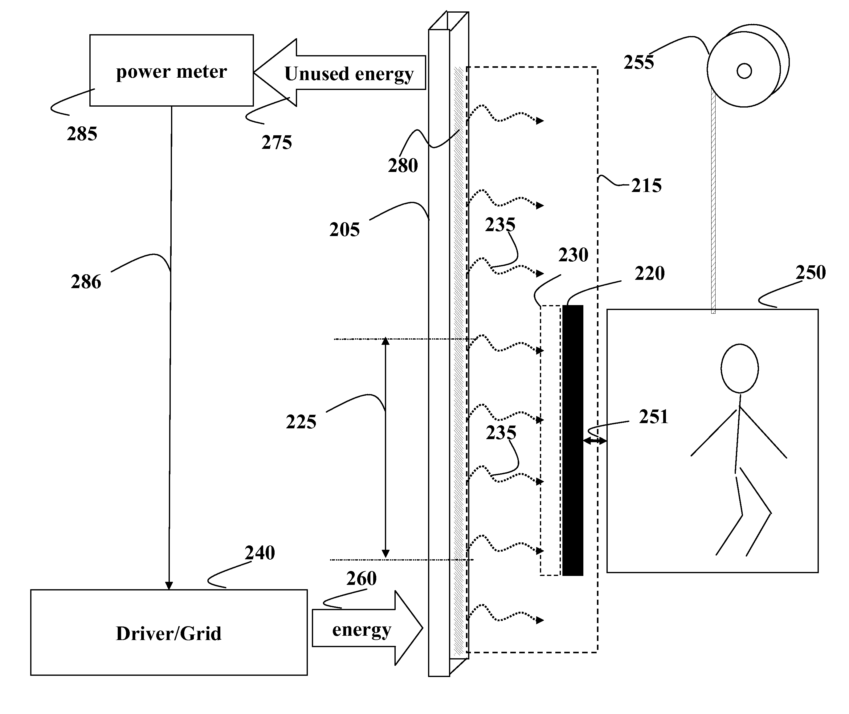
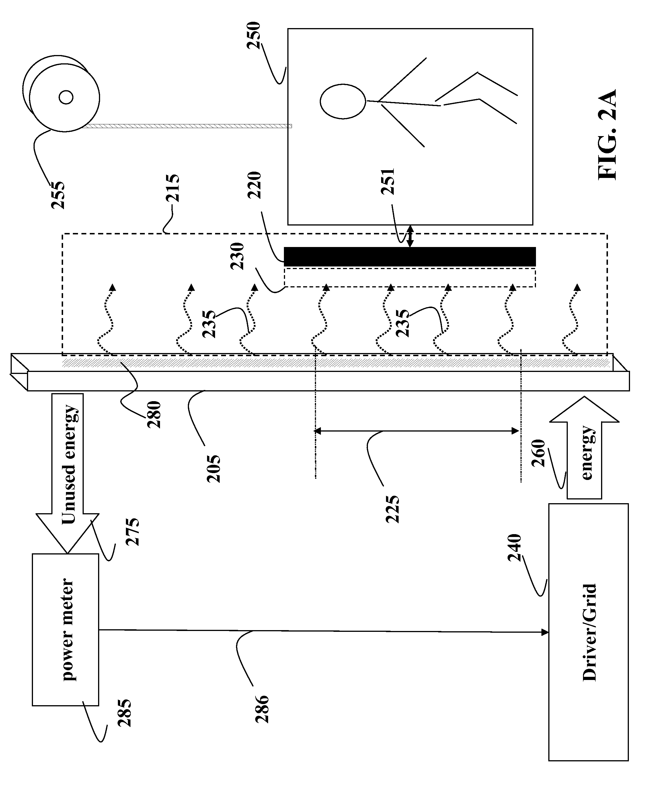
[0021]Embodiments of the invention are based on a realization that a coupling of evanescent waves between an energy source and an energy sink having at least one degree of freedom can be optimized by implementing the source as a waveguide configured to generated evanescent waves at least on a part of a surface of the waveguide and arranging the sink such that the sink moves along the waveguide while maintaining the coupling to the waveguide within an energy transfer area.

[0022]Embodiments of the invention can be used in a variety of applications, systems and devices, which require wireless energy transfer to a sink having at least one degree of freedom, e.g., a train, and an elevator car.

[0023]FIG. 2A shows an embodiment of our invention configured to optimized wireless energy transfer from the source implemented as a waveguide 205 to the sink 220 configured to move along the waveguide. In one embodiment, the sink is connected to a cable-less elevator car, i.e., a load 250, and the ...


PUM

PropertyMeasurementUnit
relative permittivityaaaaaaaaaa
transfer energyaaaaaaaaaa
energyaaaaaaaaaa

Abstract

A system exchanges energy wirelessly and includes a source configured to generate evanescent waves, in response to receiving the energy, on at least part of a surface of the source. The system also includes a sink configured to receive the energy wirelessly from the source via a coupling of the at least part of the evanescent waves and a load configured to receive the energy from the sink. The load and the sink are configured to move along the surface of the source such that the at least a part of the evanescent waves are coupled between the source and the sink within an energy transfer area.

Description

RELATED APPLICATIONS[0001]This U.S. Non-Provisional Patent Application is related to application Ser. No. 12 / 630,498, entitled “Wireless Energy Transfer with Negative Index Material,” filed Dec. 3, 2009, by Koon Hoo Teo et al., and application Ser. No. 12 / 686,466, entitled “System and Method for Energy Transfer,” filed Jan. 13, 2010, by KoOn Hoo Teo et al. both incorporated herein by reference.FIELD OF THE INVENTION[0002]The present invention relates to transferring energy, and more particularly, to transferring energy wirelessly to moving devices.BACKGROUND OF THE INVENTION[0003]Wireless Energy Transfer[0004]Inductive coupling is used in a number of wireless energy transfer applications such as charging a cordless electronic toothbrush or hybrid vehicle batteries. In coupled inductors, such as transformers, a source, e.g., primary coil, generates energy as an electromagnetic field, and a sink, e.g., a secondary coil, subtends that field such that the energy passing through the sink...

Claims


Application Information

Patent Timeline
Patent Type & Authority Patents(United States)
IPC IPC(8): H01F27/42H01F37/00H01F38/00
CPCH02J5/005B66B7/00H02J50/12
Inventor YERAZUNIS, WILLIAM S.IYER, VISHWANATHHUANG, DADUAN, CHUNJIETEO, KOON HOO
Owner MITSUBISHI ELECTRIC RES LAB INC
Why Eureka
Try Eureka