Patient lifting device

a lifting device and patient technology, applied in the field of patient lifting devices, can solve the problems of difficult adjustment, difficult movement of lifting devices, and high manufacturing cos

Inactive Publication Date: 2013-03-19
TRAXX MOBILITY SYST LLC
View PDF34 Cites 28 Cited by
  • Summary
  • Abstract
  • Description
  • Claims
  • Application Information

AI Technical Summary

Problems solved by technology

These patient lifting devices are difficult to move, difficult to adjust, and expensive to manufacture.
These cables are bulky and difficult to manipulate as the motor moves along the trolley-carrying-track.
Patient lifting devices have not been directed to allow for easy charging of the batteries for the patient lifting devices.
When it becomes necessary to lift the patient, it is not practical to await a period of time for recharging the batteries.

Method used


Image

  • Patient lifting device
  • Patient lifting device
  • Patient lifting device

Examples


Embodiment Construction

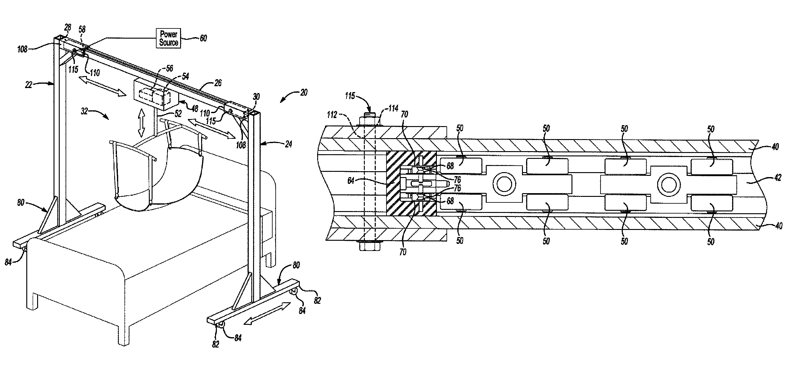
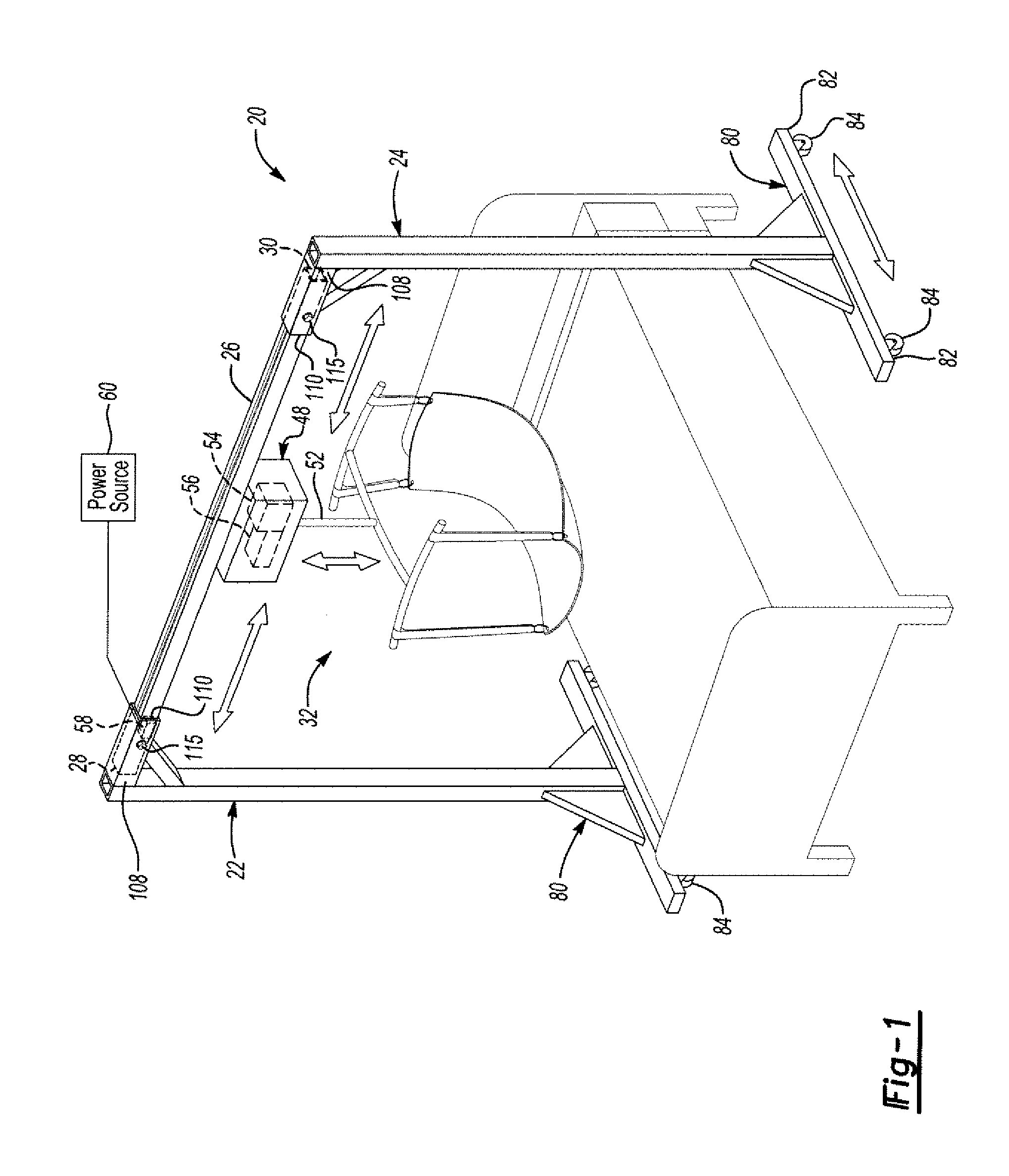
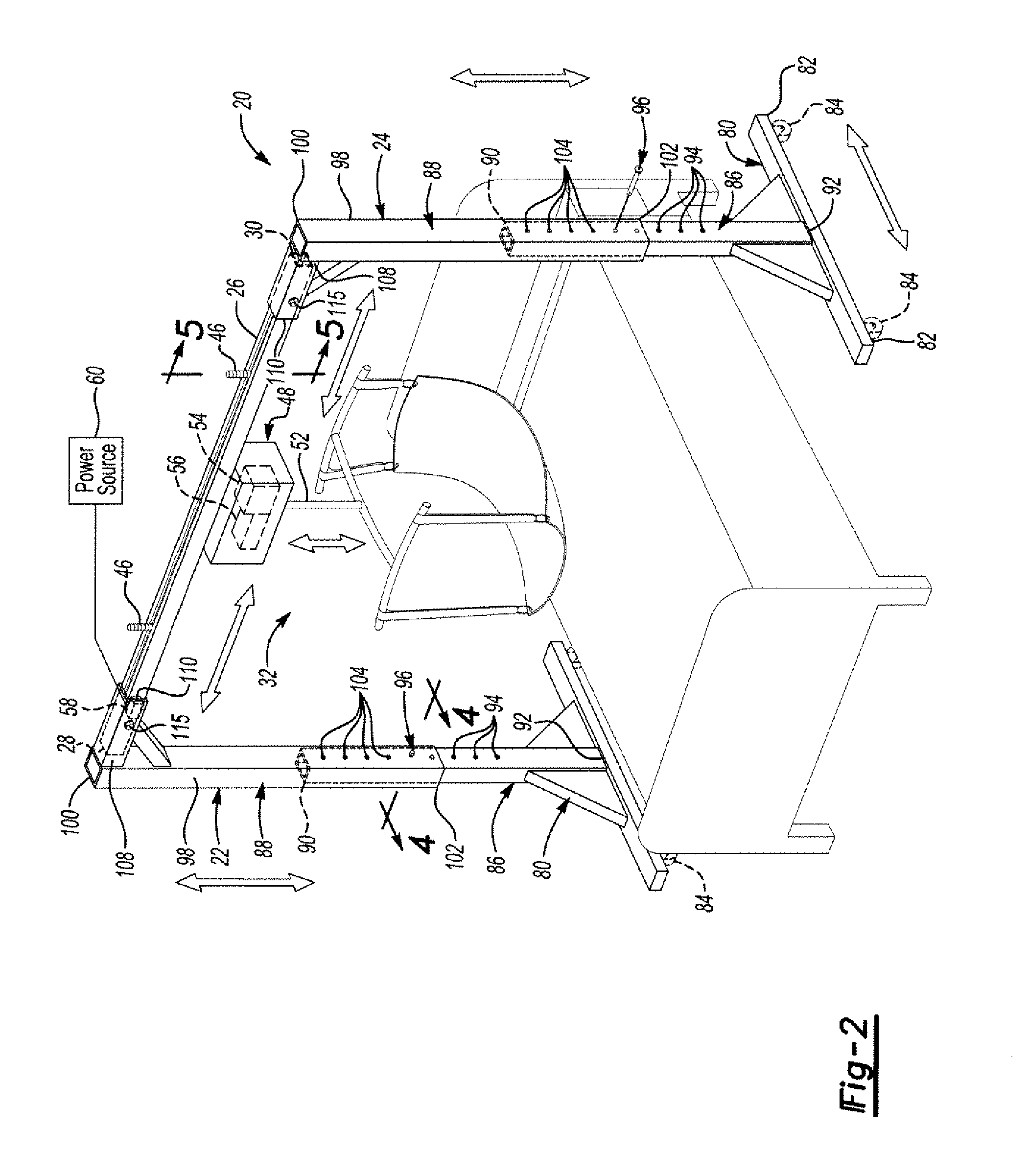
[0017]Referring to the Figures, wherein like numerals indicate corresponding parts throughout the several views, a patient lifting device 20 to move a patient relative to a bed or chair is generally shown.

[0018]The patient lifting device 20 is manufactured primarily from light weight aluminum. In one example, the aluminum portions are anodized with a satin finish. As known, such a finish facilitates cleaning. The patient lifting device 20 provides for a simplified unit that is cost effective, easy to work with, easy to assembly, and easy to maintain.

[0019]The patient lifting device 20 includes a first support structure 22 and a second support structure 24 that is spaced from the first support structure 22. A transverse beam 26, that extends between a first beam end 28 and a second beam end 30, is supported between the first and second support structures 22, 24. One of the first and second beam ends 28, 30 engages one of the first and second support structures 22, 24 while the other ...


PUM


Abstract

The patient lifting device includes a transverse beam that supports a movable lift assembly to move a patient relative to at least one of a bed or chair. The transverse beam spans between a pair of support structures and allows the lift assembly to move horizontally along the transverse beam to move the patient horizontally relative to the bed or chair. At one of the transverse beam ends, the lift assembly contacts a charging station. The charging station charges a battery, that is carried by the lift assembly, to power the lift assembly. The lift assembly is powered to move a patient vertically upward and downward. A power source is electrically coupled to the charging station to provide electrical power to charge the battery of the lift assembly through the charging station.

Description

BACKGROUND OF THE INVENTION[0001]1. Field of the Invention[0002]A patient lifting device for moving a patient relative to a bed or chair.[0003]2. Description of the Prior Art[0004]Devices have been proposed in the prior art for use in lifting invalid patients from a bed for movement about a room. As an example, there is a need to lift invalid patients from their beds for cleaning the patient, transferring the patient to a wheelchair, gurney, etc., or for the use of a toilet.[0005]Some patient lifting devices include a trolley-carrying-track spanning towers that are permanently affixed to an interior room. The trolley-carrying-track guides a take-up motor that lifts a patient from a bed or chair, for example. These patient lifting devices are difficult to move, difficult to adjust, and expensive to manufacture. Further, the take-up motor includes permanently attached cables that electrically power the motor. These cables are bulky and difficult to manipulate as the motor moves along ...

Claims


Application Information

Patent Timeline
Patent Type & Authority Patents(United States)
IPC IPC(8): A61G7/10
CPCA61G7/1015A61G7/1042A61G7/1046A61G7/1051A61G7/1055
Inventor CAPALDI, GUIDO
Owner TRAXX MOBILITY SYST LLC
Why Eureka
Try Eureka