
Interrupter arrangement having a movable switching tube

Inactive Publication Date: 2013-03-19
SIEMENS AG
View PDF16 Cites 0 Cited by
  • Summary
  • Abstract
  • Description
  • Claims
  • Application Information

AI Technical Summary

Benefits of technology

The invention aims to provide an interrupter arrangement that can move the switching tube in a complex manner while using minimal power from the drive device.

Problems solved by technology

For example, lighter-weight designs can thus be used whose structure would be at risk, at least over the long term, as a result of the influence of the switching gases, if there were no shield effect.

Method used


Image

  • Interrupter arrangement having a movable switching tube
  • Interrupter arrangement having a movable switching tube
  • Interrupter arrangement having a movable switching tube

Examples


Embodiment Construction

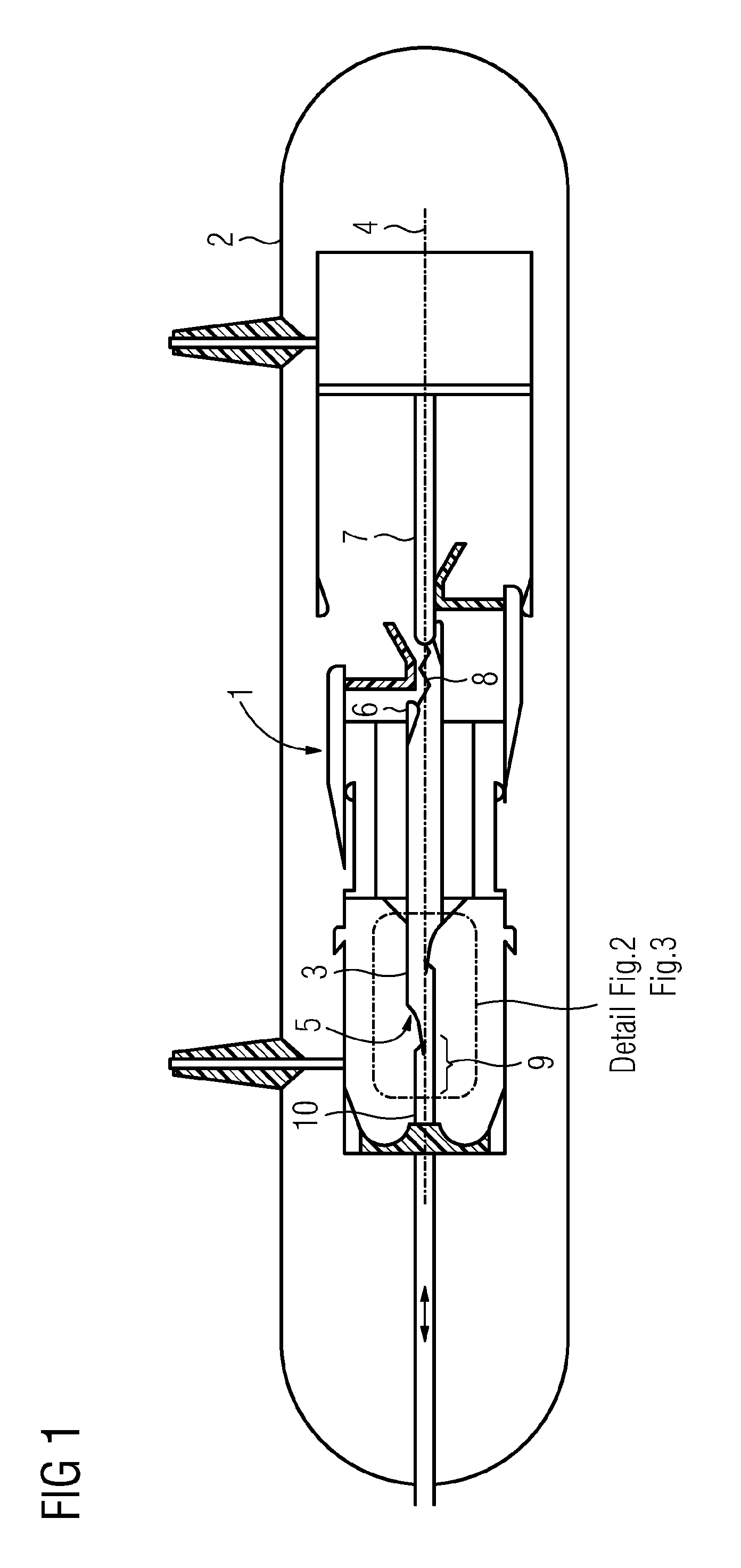
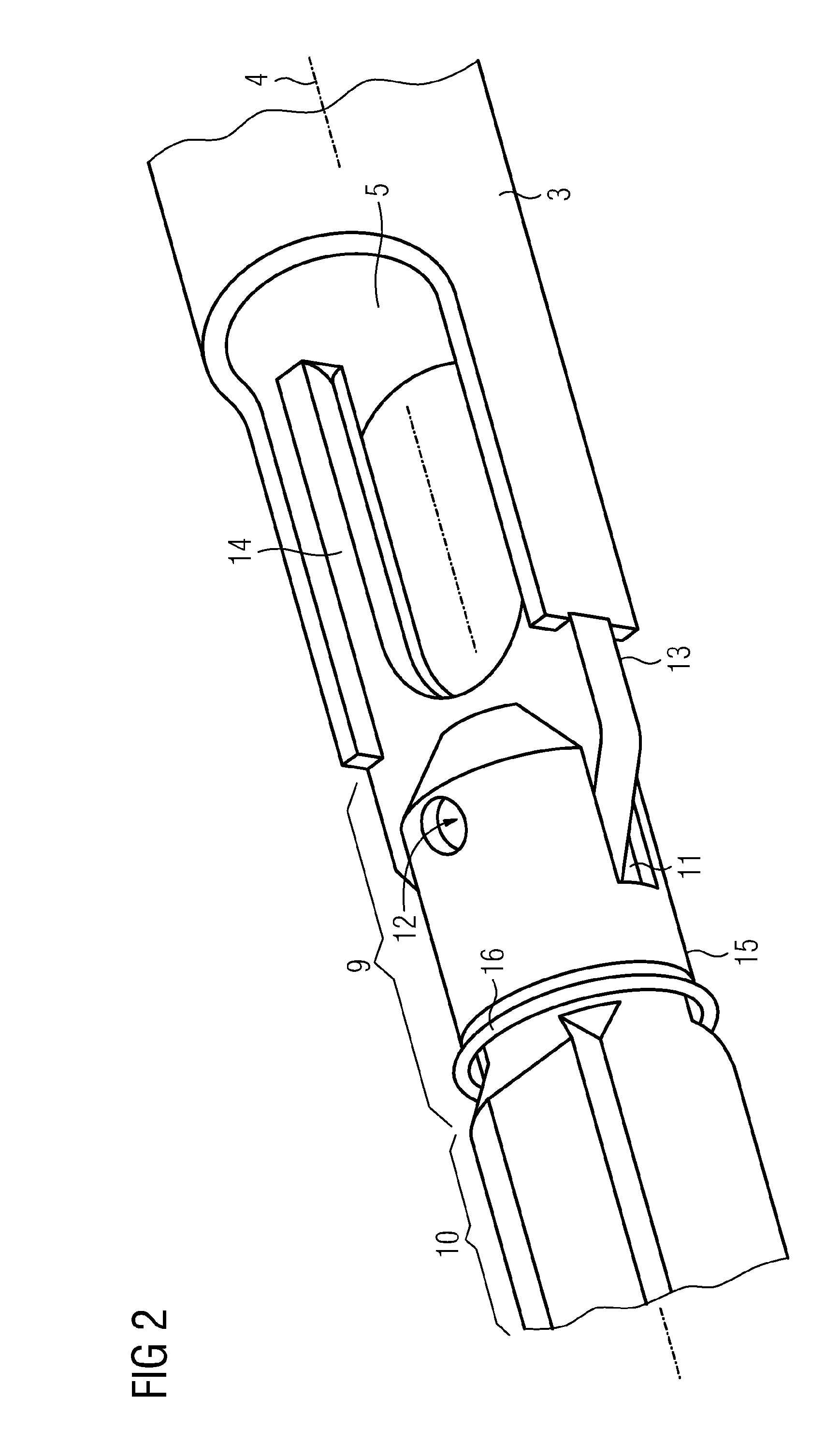
[0034]FIG. 1 shows a section though an electrical switching device. The electrical switching device has an interrupter arrangement 1 which is arranged within a gas-tight encapsulating housing 2. By way of example, the gas-tight encapsulating housing 2 is an electrically conductive structure, which is connected to ground potential. However, it is also possible for the gas-tight encapsulating housing 2 to be in the form of an electrically insulating arrangement, for example composed of porcelain covers. The interior of the gas-tight encapsulating housing 2 is filled with an electrically insulating gas, for example nitrogen or sulfur hexafluoride. This electrically insulating gas is preferably at a higher pressure than the area surrounding the gas-tight encapsulating housing 2. The electrically insulating gas is used on the one hand for electrical insulation of the interrupter arrangement 1, while on the other hand the electrically insulating gas is also used to assist interruption / que...


PUM


Abstract

The invention relates to an interrupter arrangement (1) having a switching tube (3) comprising a switch gas outlet opening (5). The switching tube (3) is connected to a coupling section (9) of a drive rod (10) in the region of the switch gas outlet opening (5). The coupling section (9) is protected from switch gasses emitted from the switch gas outlet opening (5) by means of a shield (15).

Description

BACKGROUND OF THE INVENTIONField of the Invention[0001]The invention relates to an interrupter arrangement having a movable switching tube and having a coupling section of a drive rod, which coupling section is coupled to the switching tube in the area of a switching gas outlet opening of the switching tube.[0002]One such interrupter arrangement is disclosed, for example, in French Laid-Open Specification FR 2 760 890 A1. This document describes an interrupter arrangement which has a movable switching tube to which a coupling section of a drive rod is coupled. The coupling section is located in the area of a switching gas outlet opening of the switching tube. In the known embodiment variant, the coupling section is designed such that it tapers in the direction of the switching gas outlet opening. In order to ensure an adequate life, the coupling section can be designed to have appropriate resistance to the switching gases, which in some cases are hot and aggressive.[0003]A configura...

Claims


Application Information

Patent Timeline
IPC IPC(8): H01H33/53
CPCH01H33/24H01H33/42H01H33/7015H01H2033/888
Inventor GERICKE, JOACHIMPULS, RONALD
Owner SIEMENS AG
Learn More