Device and method for friction damping

a technology of friction damping and device, applied in the field of civil engineering, can solve the problems of not allowing large-amplitude displacements in all directions to be absorbed, limited fatigue and durability performance, and not suitable for use in structures

Active Publication Date: 2016-11-03
VSL INT AG
View PDF0 Cites 0 Cited by
  • Summary
  • Abstract
  • Description
  • Claims
  • Application Information

AI Technical Summary

Benefits of technology

[0012]One aim of the present invention is to propose a damping device free from the limitations of the known devices and enabling displacements along different components between a first structural element and a second structural element of a work of construction to be dampened.

Problems solved by technology

This device does not allow large-amplitude displacements in all directions to be absorbed.
Furthermore, the implementation of systems such as described in document FR2 664 920 involves using mechanical bearings whose performance in terms of fatigue and durability are limited and which therefore are not suitable for use in structures subjected to numerous cycles of dynamic loading.
However, this solution does not make it possible to dampen, within the same damping device, several components of a large-amplitude relative movement between a first structural element and a second structural element of a work of construction.
Again, this device is not suitable for damping large-amplitude displacements along any directions.
Existing damping devices are however poorly adapted for damping such complex displacements along various components.

Method used


Image

  • Device and method for friction damping
  • Device and method for friction damping
  • Device and method for friction damping

Examples


first embodiment

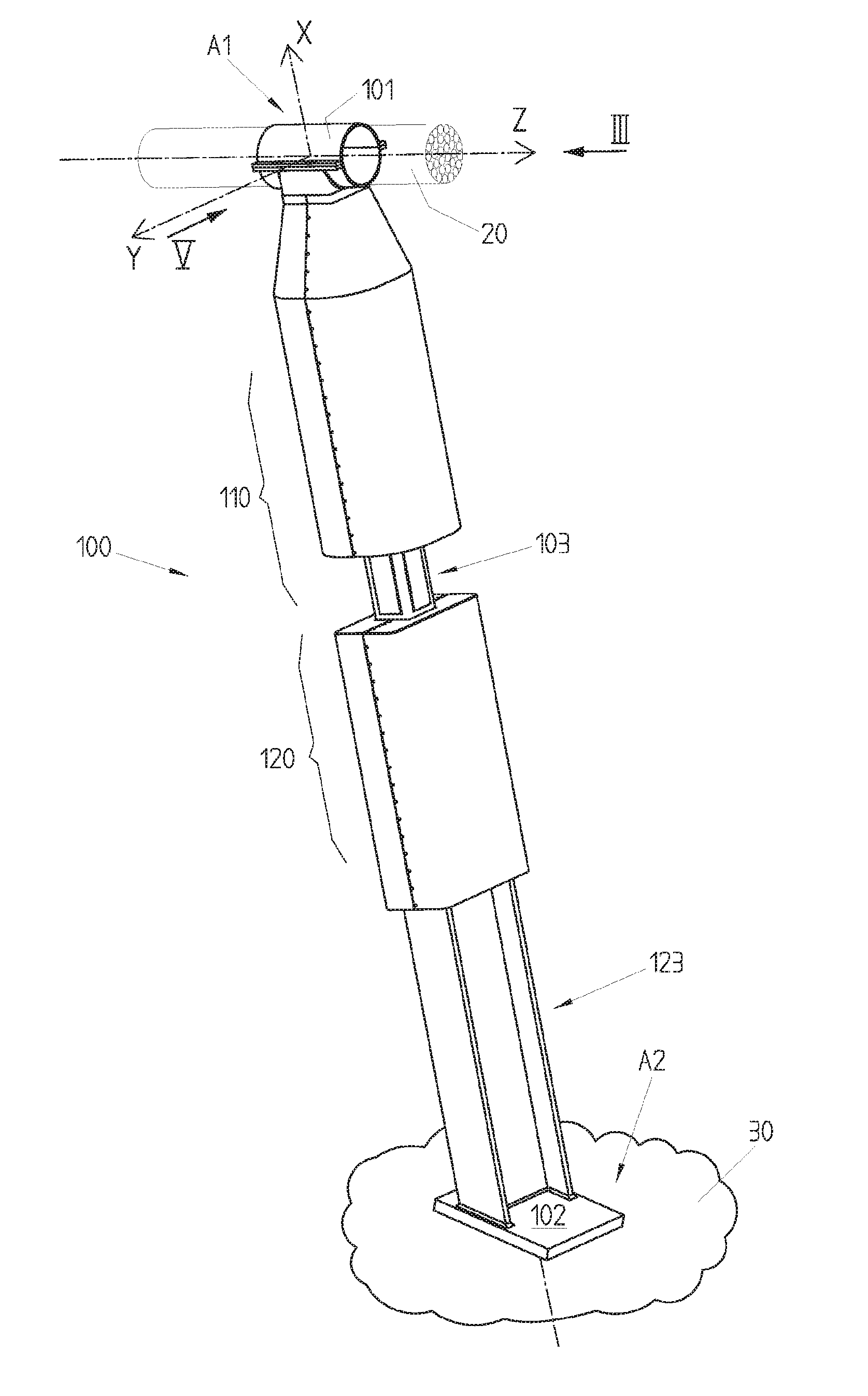
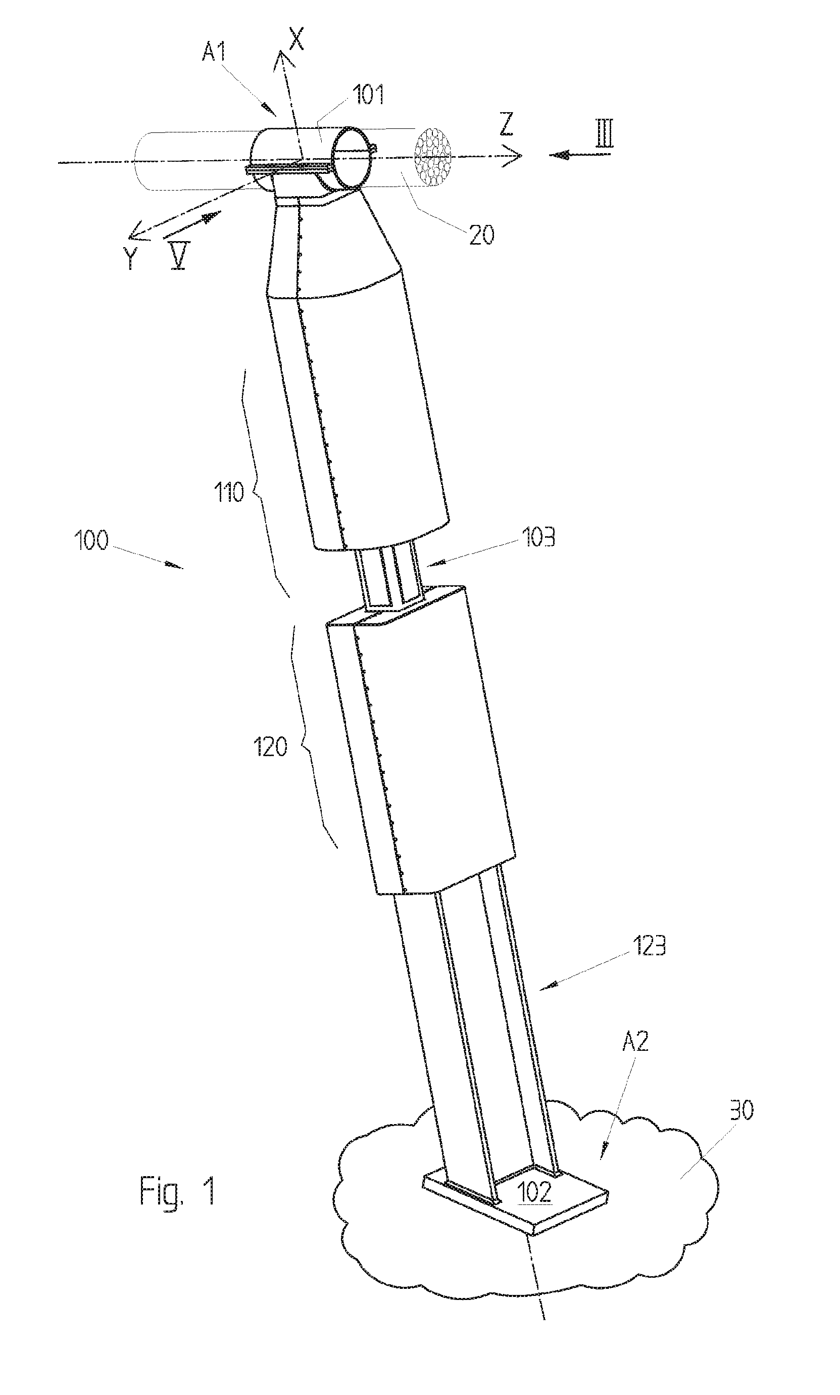
[0059]As can be seen in FIGS. 1 and 13, the damping device 100 is mounted in this example between a cable 20 or stay (forming a first structural element) and a second structural element 30, for example a foundation, a slab, the deck of a suspended bridge or else a part mounted integrally with such a deck. The cable can be connected to a pylon or strut (not represented).

[0060]With respect to the cable 20, the damping device 100 is mounted for example by a sleeve 101 enclosing the cable 20 and forming a first anchoring point A1. The sleeve 101 can be fixed relative to the cable or capable of sliding longitudinally along this cable.

[0061]With respect to the foundation 30, the damping device 100 is mounted for example by a mounting flange 102 welded or riveted to the foundation 30 and forming a second anchoring point A2.

[0062]The damping device 100 thus connects the first anchoring point A1 to the second anchoring point A2 along a first direction X corresponding to the longitudinal dir...

third embodiment

[0098]FIG. 15 illustrates a third embodiment wherein a first element 113 of the first damping system 110 is connected in an articulated manner to the sleeve 101 thanks to a shaft 131 (R″) parallel to the axis Y and enabling the element 113 to pivot around the axis Y relative to the cable 20. Furthermore, an element 123 of the second damping system 120 is connected in an articulated manner to the second structural element 30, thanks to a pivot 129 allowing a rotation around the axis R′ parallel to the axis Y and enabling the element 123 to pivot around the axis Y relative to the second structural element 30. Optionally, the sleeve 101 could still move longitudinally along the axis Z parallel to the cable 20. The shaft 131 is optional and preferably non dampened. The shaft 129 is preferably dampened by means of fifth and sixth friction surfaces 132, for example pads, between the element 123 and the stirrup 132 integral with the foundation 30.

[0099]The first element 113 can furthermore...


PUM


Abstract

The invention relates to a friction damping device (100) for damping relative movements between a first structural element and a second structural element of a construction, comprising: —a first damping system (110) for damping a first relative movement component and having a first friction surface (111) and a second friction surface (112), —a second damping system (120) for damping a second relative movement component and having a third friction element (121) and a fourth friction element (122). The first friction surface and the second friction surface of the first and the second damping system form a frictional engagement. The first damping system (110) and the second damping system (120) are placed in series.

Description

TECHNICAL FIELD[0001]The present invention concerns the field of civil engineering. In particular, the present invention concerns a device and a method for friction damping enabling the damping of relative displacements, and in particular oscillations, between a first structural element and a second structural element of a work of construction.[0002]More particularly, but in no way limited thereto, the present invention concerns a device and a method for damping vibrations of cables in a work of construction, such as the stays of a bridge, of a roof, of a suspended walkway, of structural elements potentially subjected to vibrations or large-amplitude displacements or any other suspended work of construction.STATE OF THE ART[0003]In civil engineering works, different structural elements are frequently subjected to relative displacements, for example relative movements or relative vibrations.[0004]It is known to dampen such relative displacements by using viscoelastic means or means a...

Claims


Application Information

Patent Timeline
Patent Type & Authority Applications(United States)
IPC IPC(8): E01D19/16F16F7/08
CPCF16F7/08E01D19/16E01D19/00E04H9/021E01D11/00E04H9/0235F16F9/18
Inventor ANNAN, RACHID
Owner VSL INT AG
Why Eureka
Try Eureka