Medical support system

a technology of medical support and support rod, which is applied in the field of medical support rod, can solve the problems of slow and awkward displacement of such patients, manipulated by a plurality of attendants,

Inactive Publication Date: 2013-03-26
8043523 CANADA
View PDF35 Cites 19 Cited by
  • Summary
  • Abstract
  • Description
  • Claims
  • Application Information

AI Technical Summary

Problems solved by technology

This results in the slow and awkward displacement of such patients.
One of the issues associated with such locking systems is that they are manipulated by a plurality of attendants.

Method used


Image

  • Medical support system
  • Medical support system
  • Medical support system

Examples


Embodiment Construction

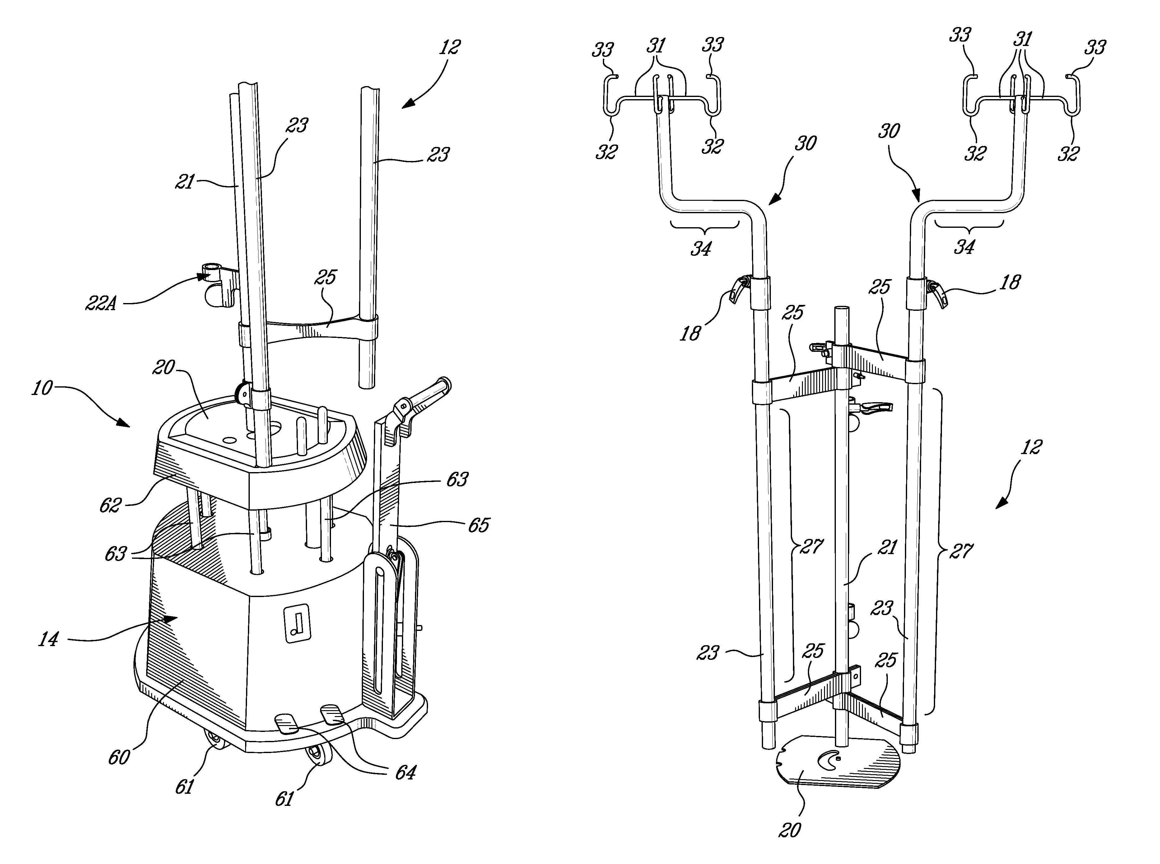
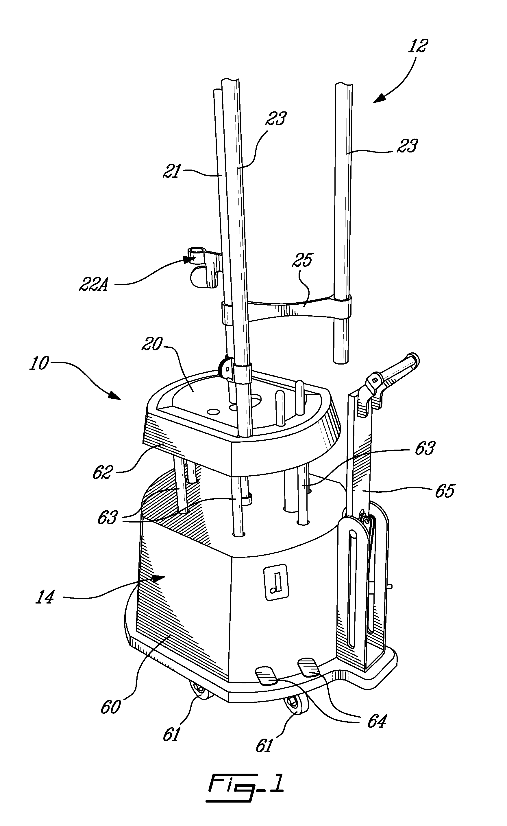
[0022]Referring now to the drawings and, more particularly to FIG. 1, a medical support system in accordance with a first embodiment is generally shown at 10. The medical support system 10 has a support frame 12 and a wheeled stand 14. A wall support 16, as illustrated in FIG. 3, is part of the medical support system 10.

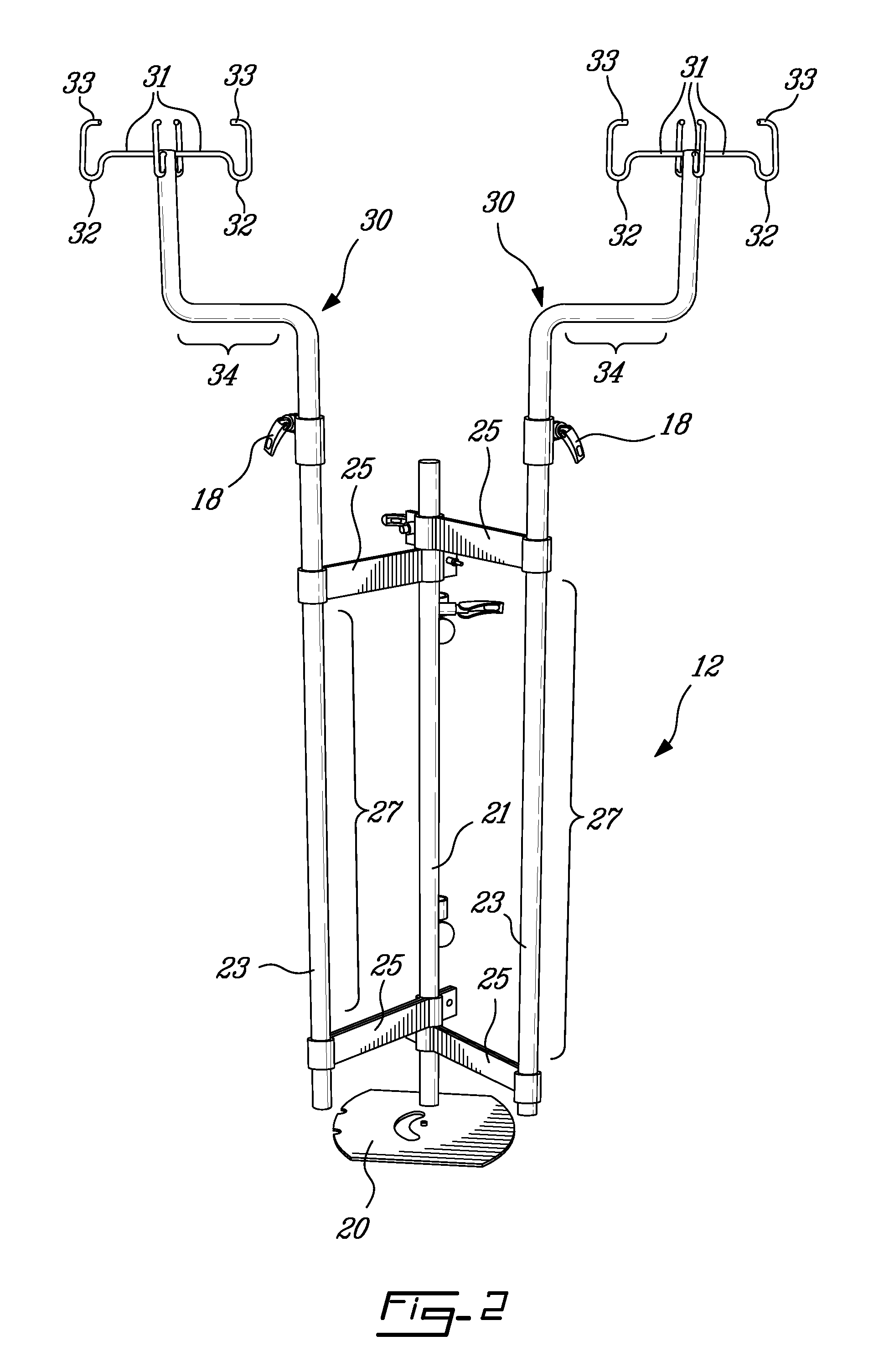
[0023]The support frame 12 is provided to support intravenous bags, as well as associated mechanical apparatuses, such as pumps (e.g., volumetric pumps) and monitoring devices.

[0024]The wheeled stand 14 is provided to support the support frame 12, and facilitate displacements thereof. The support frame 12 may be mounted directly onto a bed as well.

[0025]The wall support 16 is typically positioned adjacent to the patient's bed, and is provided to support the support frame 12. The wall support 16 may be provided with a railing system, so as to be displaceable within a room along a wall.

[0026]Referring to FIG. 1, connector mechanisms 18 are provided on the support frame...


PUM


Abstract

A support frame for supporting an intravenous bag and associated equipment, comprises a main pole adapted to be secured to a structure so as to be self-standing. A pivotable pole is adapted to support equipment associated with an intravenous bag. A pivot joint is provided between the main pole and the pivotable pole such that the pivotable pole rotates about the main pole. A rack is supported by the pivotable pole, the rack being adapted to support an intravenous bag.

Description

CROSS-REFERENCE TO RELATED APPLICATIONS[0001]This patent application is a continuation of PCT Patent Application No. PCT / CA2007 / 002349, filed on Dec. 21, 2007, and claims priority on United States Provisional Patent Application No. 60 / 871,157, filed on Dec. 21, 2006.BACKGROUND OF THE APPLICATION[0002]1. Field of the Application[0003]The present application relates to a medical support system for supporting intravenous bags and associated mechanical equipment.[0004]2. Background Art[0005]Solutions of nutritional fluids are often supplied to patients intravenously. In many instances, a stand supports a fluid bag adjacent to a patient, and mechanical apparatuses such as pumps and monitoring devices are optionally provided in association with the intravenous tubing while being supported by the stand. Intravenous bag stands are often provided with casters, in order to follow the patient in his / her displacements.[0006]When patients in wheelchairs, hospital beds or carts are displaced whil...

Claims


Application Information

Patent Timeline
Patent Type & Authority Patents(United States)
IPC IPC(8): A47K1/04
CPCA61M5/1415
Inventor COTE, JOCELYN
Owner 8043523 CANADA
Why Eureka
Try Eureka