
Vibration pickup microphone

a pickup microphone and microphone technology, applied in the field of vibration pickup microphones, can solve the problems of low sensitivity and large structure, low sensitivity of other parts than the diaphragm to vibration, and the anti-noise characteristic is somewhat degraded when used in high ambient noise environments, so as to achieve good bone vibration pickup characteristic and not easily pick up air-conduction sound.

Inactive Publication Date: 2013-04-09
TEMCO JAPAN
View PDF7 Cites 3 Cited by
  • Summary
  • Abstract
  • Description
  • Claims
  • Application Information

AI Technical Summary

Benefits of technology

The present invention provides a way to make a microphone that picks up vibrations but doesn't pick up air-conduction sounds. This is done by using a thin passageway that reduces high frequencies through viscous friction. This results in a smaller microphone that still picks up vibrations well. Overall, the invention allows for a more accurate and reliable way to pick up vibrations and bone-conduction sounds.

Problems solved by technology

This type of microphone is in common use since it is highly sensitive while resistant to external noise, but it has drawbacks that it is sensitive to sliding noise and its frequency response is not flat (a large resonance peak for its element occurs).
However, the dynamic microphone has drawbacks that it has low sensitivity and is large structurally.
This is because the vibration is picked up only by its diaphragm, and any portions other than the diaphragm have extremely low sensitivity to vibration.
In this way, though this type of microphone has advantages of having high microphone sensitivity and resistance to sliding noise, it has also a drawback that its anti-noise characteristic is somewhat degraded when used in high ambient noise environments.

Method used


Image

  • Vibration pickup microphone
  • Vibration pickup microphone
  • Vibration pickup microphone

Examples


Embodiment Construction

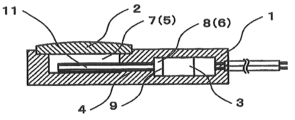
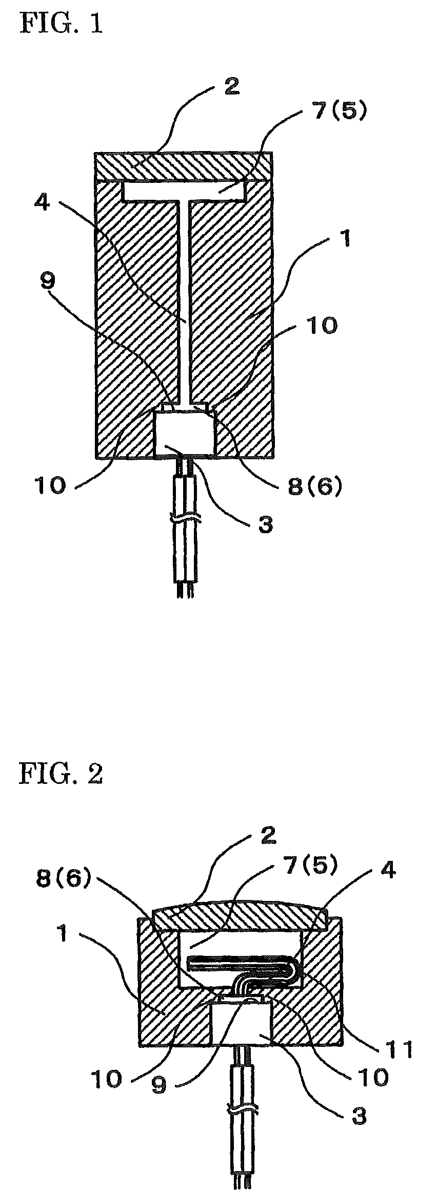
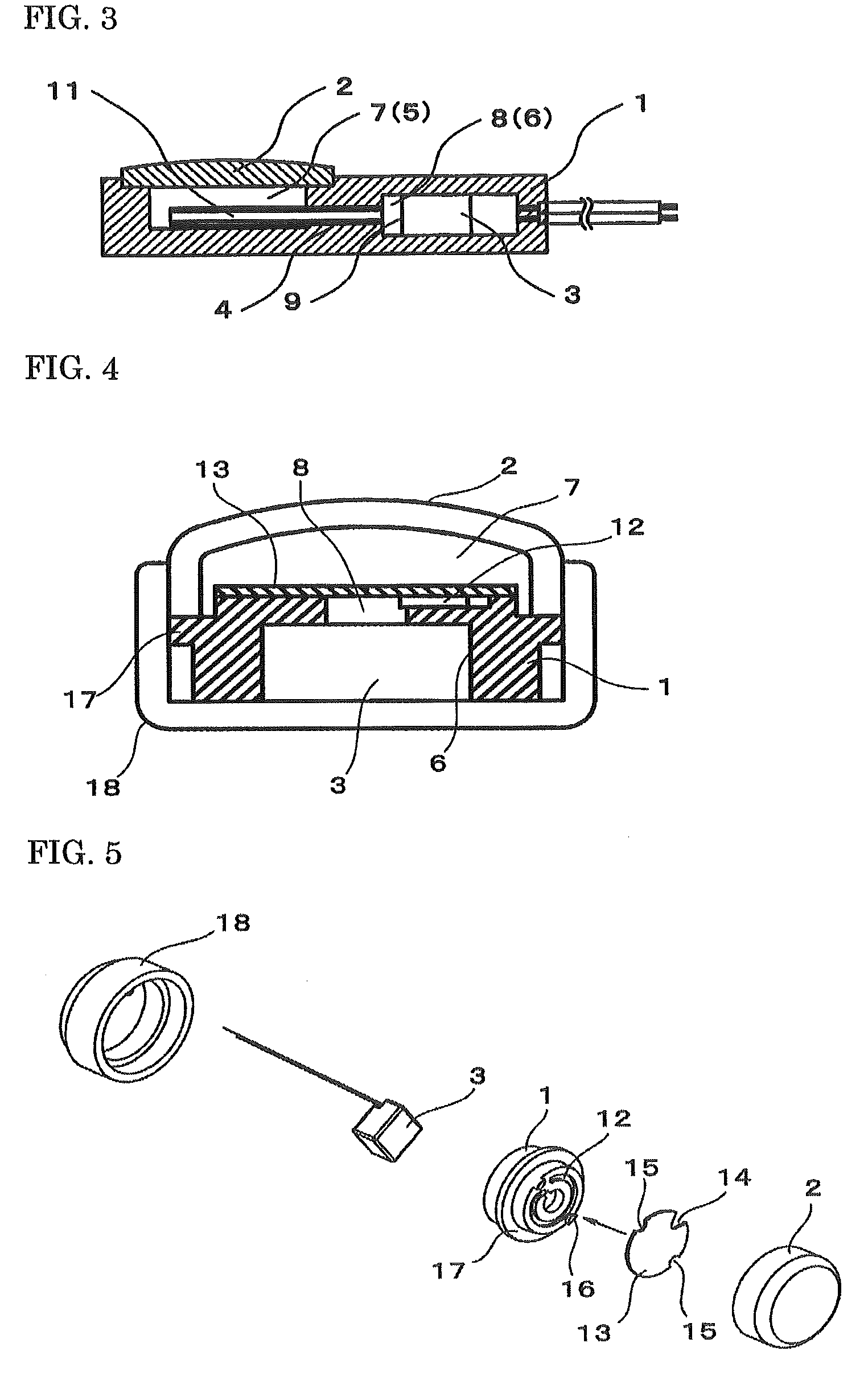
[0018]The best mode for carrying out the present invention will be described on the basis of accompanying drawings. FIGS. 1 to 3 are vertical cross-sectional views showing respective different embodiments of a vibration pickup microphone according to the present invention.

[0019]The vibration pickup microphone according to the present invention, for example, comprises a housing 1 provided with a first space 5 with its top surface open on a topside of the housing 1 and a second space 6 to contain a microphone unit 3 on an underside of the housing 1, an external diaphragm 2 disposed over an hole of the first space 5, and the microphone unit 3 that is contained in the second space 6 having an air gap 8 maintained in a rear end portion of the second space 6. By disposing the external diaphragm 2 over the hole of the first space 5, an air chamber 7 formed in the first space 5 and an air gap 8 formed in the second space 6 are communicated via a thin passageway 4.

[0020]The housing 1 is usua...


PUM


Abstract

[Problem to be Solved] To provide a high-sensitive compact vibration pickup microphone, suitably used as a talking microphone in high ambient noise environments or as a speech recognition input microphone, with high microphone sensitivity, resistance to sliding noise, and insensitivity to external noise and vibration.[Solution] A vibration pickup microphone comprising a housing 1 provided with a first space 5 and a second space 6, an external diaphragm 2 disposed over the first space 5, and a microphone unit 3 that is contained in a rear end portion of the second space having an air gap 8 maintained 6, wherein by disposing the external diaphragm 2 over it, an air chamber 7 formed in the first space 5 and an air gap 8 formed in the second space 6 are communicated via a thin passageway 4, so that vibration of voice picked up by the external diaphragm 2 is transmitted to the microphone unit 3 as sound waves, and then frequency components higher than voice frequencies within frequency components of the sound waves are attenuated in its transmitting path.

Description

TECHNICAL FIELD[0001]The present invention relates to a vibration pickup microphone, and more particularly, a type of vibration pickup microphone that picks up bone vibration and vocal fold vibration.BACKGROUND ART[0002]Microphones insensitive to external noise and picking up only a speaker's voice include a bone conduction microphone and a throat microphone. A typical bone conduction microphone for picking up bone vibration is an acceleration pickup microphone which uses a piezoelectric element supported by a supporting portion, as shown in FIG. 8.[0003]This type of microphone is in common use since it is highly sensitive while resistant to external noise, but it has drawbacks that it is sensitive to sliding noise and its frequency response is not flat (a large resonance peak for its element occurs).[0004]Also, a dynamic microphone is known, as shown in FIG. 9. The dynamic microphone has advantages of being resistant to sliding noise and easy to use because the frequency response t...

Claims


Application Information

Patent Timeline
Patent Type & Authority Patents(United States)
IPC IPC(8): H04R9/08
CPCH04R1/222H04R1/2853H04R1/083H04R1/14H04R2460/13H04R1/46H04R19/016H04R1/00H04R1/02H04R1/28H04R19/01
Inventor FUKUDA, MIKIO
Owner TEMCO JAPAN
Learn More