Irrigation fitting tool device

a tool device and fitting technology, applied in the field of clamping tools, can solve the problems of slipping consistency of fittings and tubing, process both frustrating and time-consuming, and difficulty in insertion and removal of fittings

Active Publication Date: 2013-04-16
RISLEY SR WILLIAM B +1
View PDF32 Cites 7 Cited by
  • Summary
  • Abstract
  • Description
  • Claims
  • Application Information

AI Technical Summary

Problems solved by technology

Problems exist when drip systems are installed or maintained because of the flexibility of the irrigation tubing, the rigidity of the aperture for receiving a fitting, and the general slippery consistency of the fittings and tubing.
These contributing factors tend to make the process both frustrating and time-consuming.
Additionally, the rigidity of the aperture for receiving the fitting results in a high friction relationship between the fitting and the tubing resulting in difficulty of insertion and removal of the fitting due to the high finger pressure required to insert or remove the fitting from the tubing.
The tubing tends to kink rendering it damaged and susceptible to future cracking thereby potentially introducing leaks to the system.
Valuable time and materials may be wasted, increasing overall project costs.
Increases in utility costs and water damage to adjacent structures may result if damages to the system are not noticed immediately.
Angled cuts allow less surface contact area for connection and may reduce effectiveness and efficiency of the drip system due to leaks and possible contamination by external environmental elements.

Method used


Image

  • Irrigation fitting tool device
  • Irrigation fitting tool device
  • Irrigation fitting tool device

Examples


Embodiment Construction

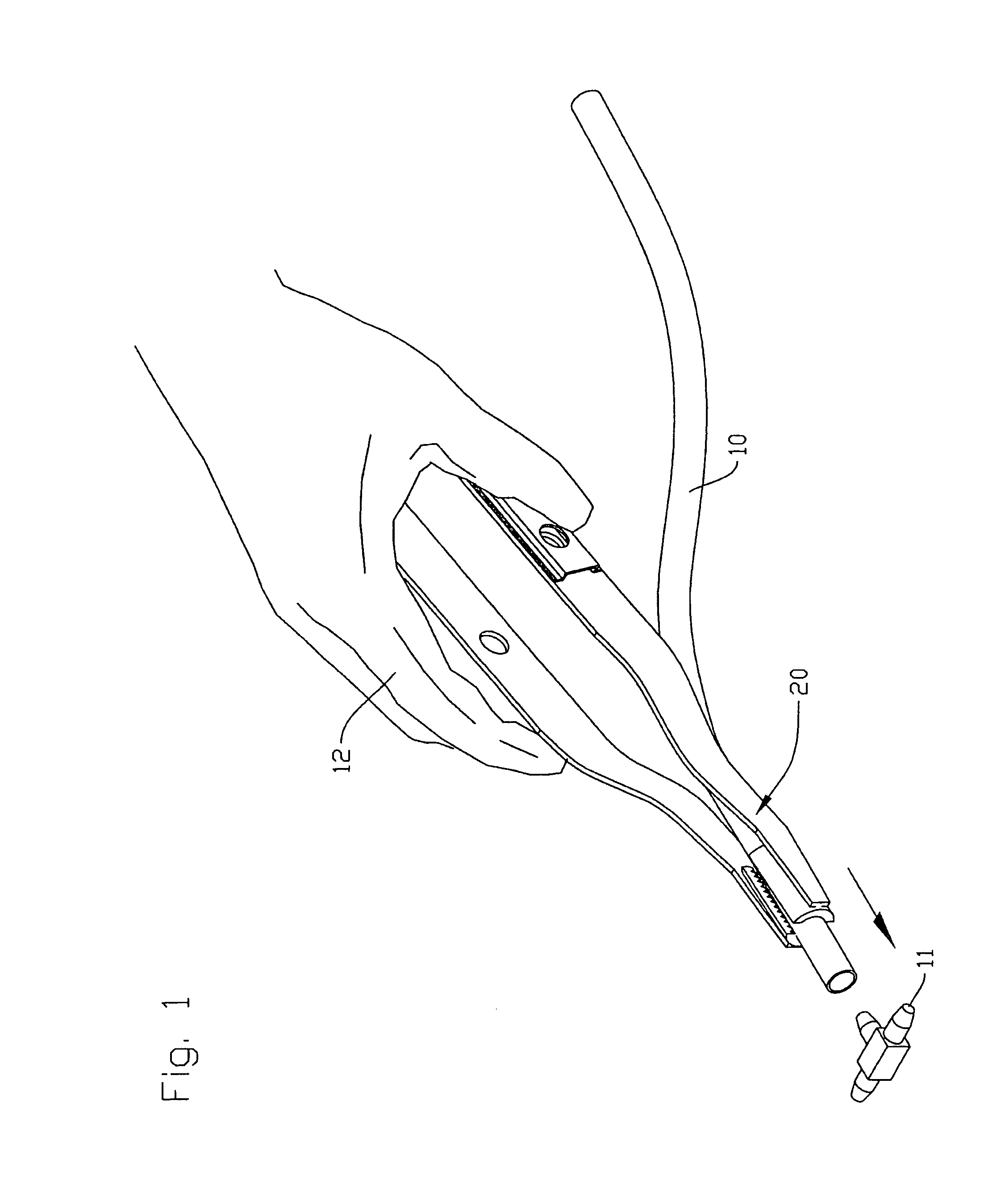
[0017]Turning now to the drawings, in which like reference characters indicate corresponding elements throughout the several views, attention is first directed to FIG. 1 in which is seen tubing 10, which may be commercial irrigation tubing preferably made of rubber, plastic or other suitable material, fitting 11, which may be a commercially available irrigation tube fitting, and a person's hand 12. Also seen is a tool device embodying the principles of the present invention and generally designated by the reference character 20. Person's hand 12 is shown as it may appear when gripping tool device 20.

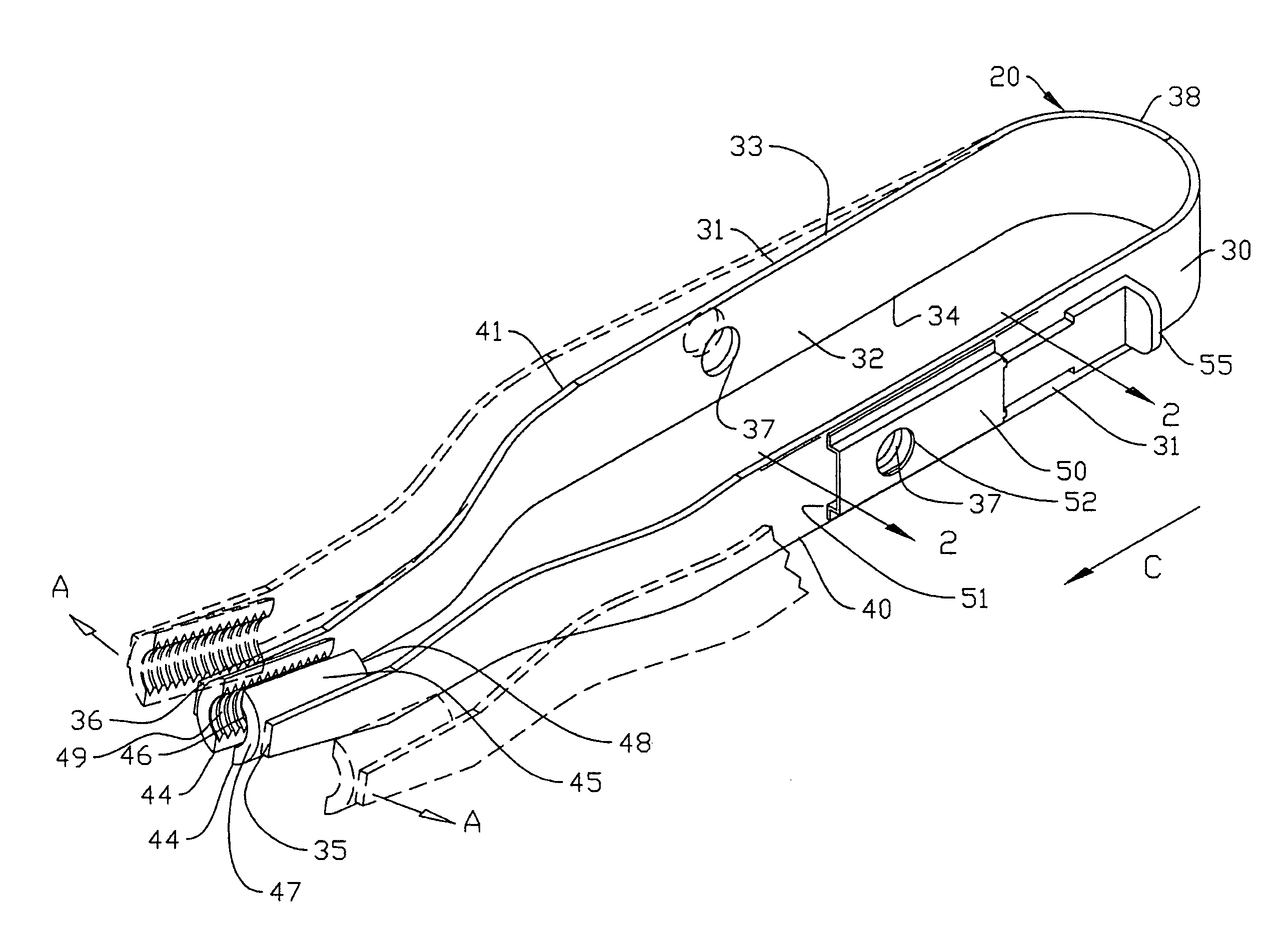
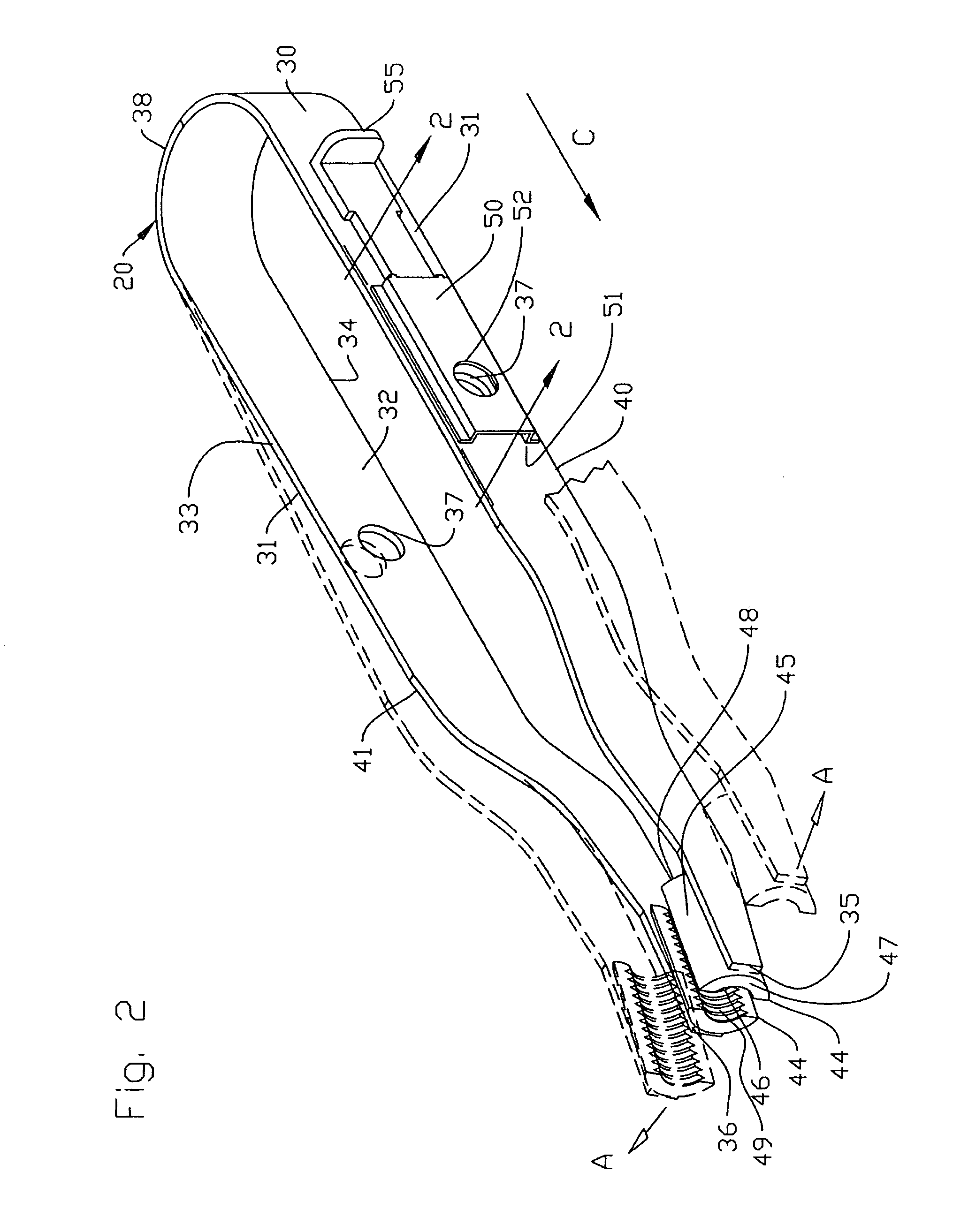
[0018]In FIG. 2 is seen tool device 20 including body 30 having outer surface 31, inner surface 32, upper edge 33, lower edge 34, end 35, end 36, a plurality of opening 37. Distal end 35 and end 36, body cooperates to form curved area 38 and coextensive members 40 and 41 providing relative movement between a gripping position and a release position, as shown in phantom. The direction of ...


PUM

PropertyMeasurementUnit
radiusaaaaaaaaaa
lengthaaaaaaaaaa
distanceaaaaaaaaaa

Abstract

The present invention is an apparatus for use with irrigation systems. The tool may be used for connecting and removing sprinkler fittings for drip systems. The irrigation tubing may be held between the rotatable tool jaws located near the ends of coextensive members of the tool, allowing a user to easily install or uninstall sprinkler fittings from the irrigation tubing. The tool provides a cutter to accurately sheer the irrigation tubing while it is securely held in place in through holes located in the coextensive members.

Description

CROSS-REFERENCE TO RELATED APPLICATION[0001]The present application is related to and claims priority from prior U.S. provisional application Ser. No. 60 / 998,588, filed Oct. 12, 2007, entitled “DRIP SYSTEM SPRINKLER FITTING TOOL DEVICE”, the contents of which are incorporated herein by reference.BACKGROUND OF THE INVENTION[0002]1. Field of the Invention[0003]The present invention relates generally to the field of clamping tools and more specifically relates to an apparatus used for installing or uninstalling sprinkler fittings for irrigation drip systems.[0004]2. Description of the Related Art[0005]Problems exist when drip systems are installed or maintained because of the flexibility of the irrigation tubing, the rigidity of the aperture for receiving a fitting, and the general slippery consistency of the fittings and tubing. These contributing factors tend to make the process both frustrating and time-consuming. The flexibility and slippery consistency of the tubing prevents the i...

Claims


Application Information

Patent Timeline
Patent Type & Authority Patents(United States)
IPC IPC(8): B26B17/00B23P19/04
CPCB26B29/06B25B27/10B25B9/02Y10T29/539
Inventor RISLEY, SR., WILLIAM B.RISLEY, MARGARET J.
Owner RISLEY SR WILLIAM B
Why Eureka
Try Eureka