Image forming apparatus including transfer roller with concave portion and image forming method

a technology of concave portion and transfer roller, which is applied in the direction of electrographic process apparatus, instruments, optics, etc., can solve the problems of cyclical fluctuation of contact with the image bearing member, no longer perfect cylindrical circumferential surface of the transfer roller, and the possibility of recording material sticking to the image bearing member. , to achieve the effect of preventing the fluctuation of the speed of the transfer roller

Inactive Publication Date: 2013-04-16
SEIKO EPSON CORP
View PDF7 Cites 0 Cited by
  • Summary
  • Abstract
  • Description
  • Claims
  • Application Information

AI Technical Summary

Benefits of technology

[0006]An advantage of some aspects of the invention is to provide, in an image forming apparatus provided with an image bearing member that bears an image and a transfer roller that makes contact with the image bearing member and that has a concave portion in its circumferential surface, and in a method for forming an image using such an image forming apparatus, a technique for suppressing fluctuations in the speed of the image bearing member and preventing disturbances in images caused by such fluctuations.
[0010]In the case where the circumferential surface of the transfer roller that faces the image bearing member is not a uniform cylindrical surface and instead has a concave portion in one part thereof, the torque required to rotate the transfer roller increases suddenly particularly when the surface of the transfer roller that faces the image bearing member changes from the concave portion to the circumferential surface aside from the concave portion, the transfer roller and the image bearing member make contact with each other, and the transfer nip is formed. Such a fluctuation in the torque leads to fluctuations in the speed of the image bearing member, which in turn causes disturbances in the formation of the image on the image bearing member. In response to this, with the aspect of the invention configured as described above, when the transfer roller makes contact with the image bearing member, the transfer roller makes contact with the image bearing member while moving away from the image bearing member. Accordingly, a sudden torque increase occurring when the transfer roller and the image bearing member make contact with each other is softened, and fluctuations in the speed of the image bearing member caused by torque fluctuations are suppressed. It is thus possible to reduce disturbances in the image caused by fluctuations in the speed of the image bearing member.
[0011]In the stated image forming apparatus, an adjustment unit that, for example, moves the rotational axis of the transfer roller closer to or away from the image bearing member may be further provided. Doing so makes it possible to maintain an appropriate interval between the rotational axis of the transfer roller and the image bearing member and impart an appropriate contact pressure between the two when the transfer nip is formed, and also makes it possible to soften an increase in the torque when the two come into contact with each other.
[0012]More specifically, the adjustment unit may include, for example, a biasing member that biases the transfer roller toward the image bearing member and a holding member that holds the distance between the rotational axis and the image bearing member against the bias exerted by the biasing member. By biasing the transfer roller toward the image bearing member and controlling the interval between the rotational axis thereof and the image bearing member, it is possible both to control the contact pressure at the transfer nip and soften an increase in the torque at the time of contact. Note that the holding member may be a member that functions only when the concave portion of the transfer roller is facing the image bearing member.
[0014]In this case, the distance between the rotational axis and the image bearing member when the circumferential surface of the transfer roller aside from the concave portion makes contact with the image bearing member due to the rotation of the transfer roller may be made less than the distance between the rotational axis and the image bearing member when the circumferential surface of the transfer roller aside from the concave portion has made contact with the image bearing member and rotated for a predetermined amount of time. Alternatively, the distance between the rotational axis and the image bearing member may become maximum after the transfer roller and the image bearing member have made contact with each other, and the distance between the rotational axis and the image bearing member may then decrease with the rotation of the transfer roller after the distance between the rotational axis and the image bearing member has become maximum. According to either of these methods, the rotational axis of the transfer roller and the image bearing member move relative to each other so as to move away from each other when the circumferential surface of the transfer roller makes contact with the image bearing member, which makes it possible to soften sudden fluctuations in the torque at the time of the contact.
[0016]In addition, for example, a gripping portion that grips the recording material onto which the image is transferred may be provided in the concave portion. Providing such a gripping portion makes it possible to prevent, with certainty, the recording material from sticking to the image bearing member at the transfer nip. In this aspect of the invention, because providing the concave portion in the transfer roller prevents fluctuations in the speeds of the transfer roller, the image bearing member, and the like from affecting the image formation, providing the concave portion in the transfer roller and the gripping portion in the concave portion makes it possible to prevent, with certainty, the recording material from sticking to the image bearing member, without affecting the image formation.

Problems solved by technology

When a contact pressure applied to the recording material at the transfer nip increases, so does the likelihood that a problem in which the recording material sticks to the image bearing member will occur.
However, if such a measure is taken, the circumferential surface of the transfer roller will no longer have a perfect cylindrical surface, and as a result, the state of contact with the image bearing member will fluctuate in a cyclical manner as the transfer roller rotates.
Such a fluctuation in the torque causes fluctuations in the speeds of the transfer roller and the image bearing member, which in turn inhibits stable image formation on the image bearing member.
Such a fluctuation in the torque leads to fluctuations in the speed of the image bearing member, which in turn causes disturbances in the formation of the image on the image bearing member.

Method used


Image

  • Image forming apparatus including transfer roller with concave portion and image forming method
  • Image forming apparatus including transfer roller with concave portion and image forming method
  • Image forming apparatus including transfer roller with concave portion and image forming method

Examples


Embodiment Construction

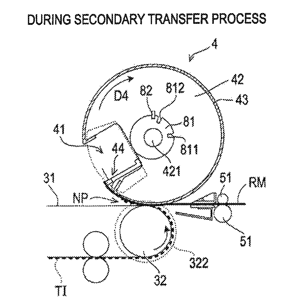
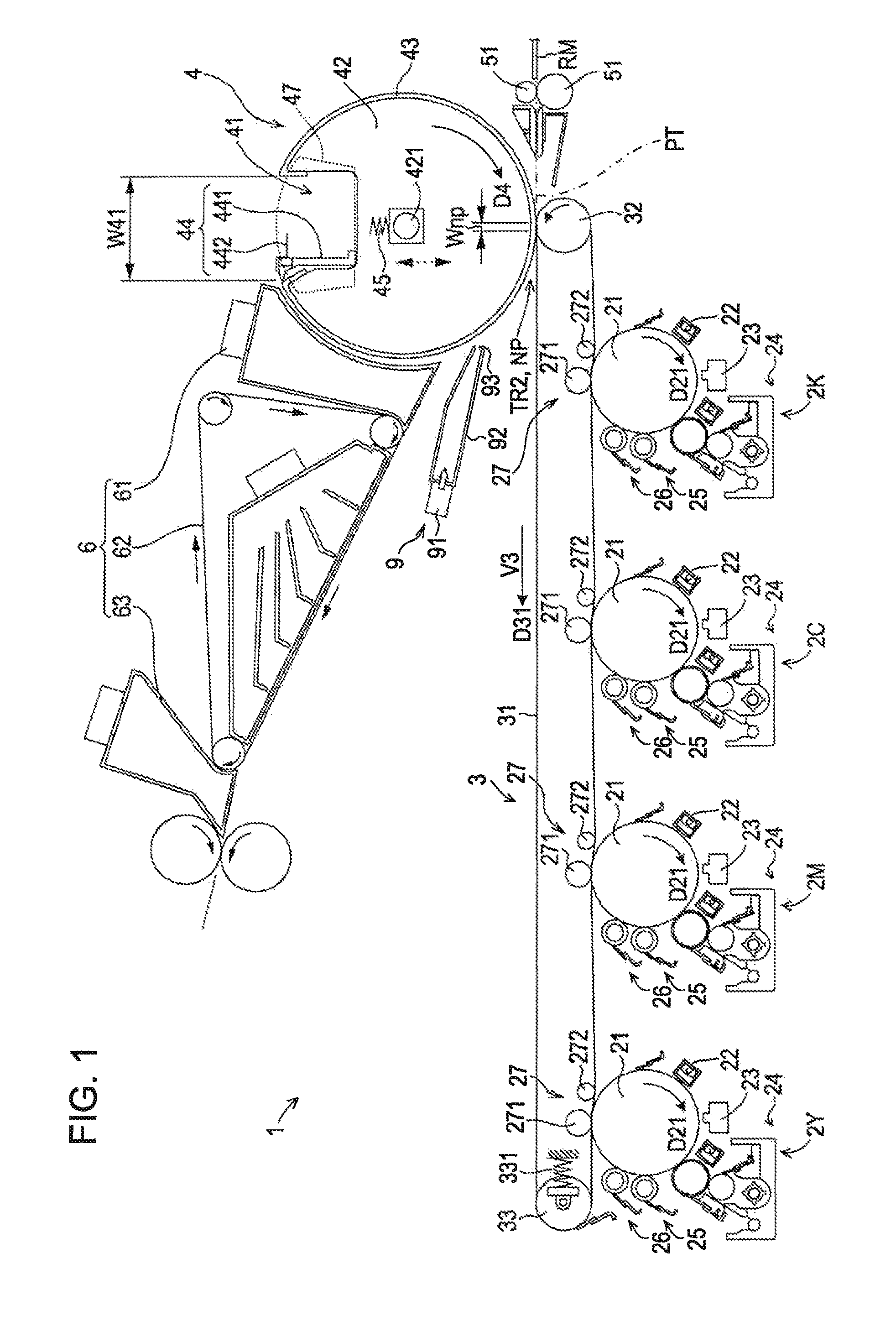
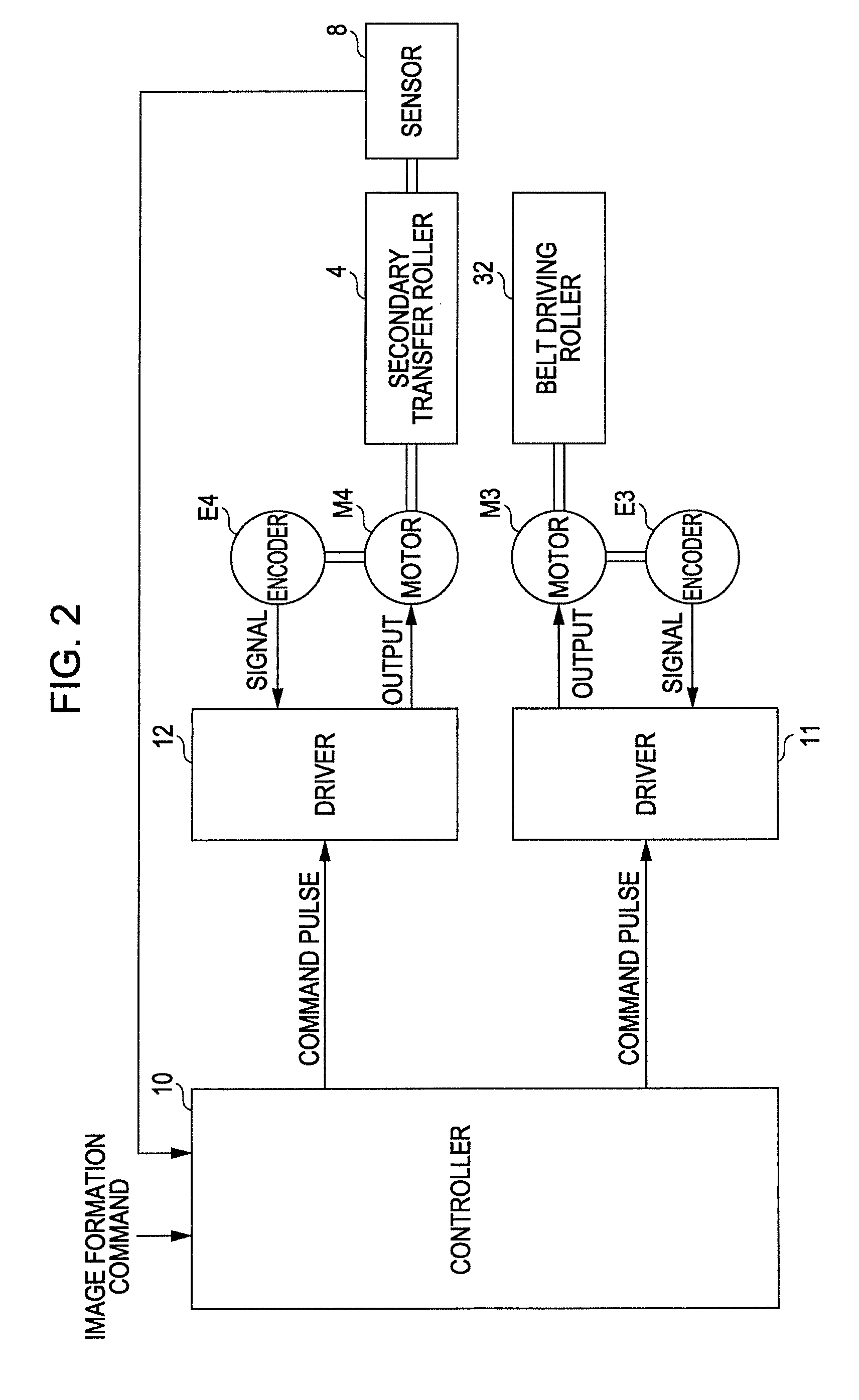
[0029]FIG. 1 is a diagram illustrating an embodiment of an image forming apparatus according to the invention. FIG. 2, meanwhile, is a block diagram illustrating an electrical configuration of the image forming apparatus illustrated in FIG. 1. An image forming apparatus 1 includes four image forming stations, or 2Y (for yellow), 2M (for magenta), 2C (for cyan), and 2K (for black), that form images of their respective colors. The image forming apparatus 1 is capable of selectively executing a color mode, in which a color image is formed by superimposing yellow (Y), magenta (M), cyan (C), and black (K) toners upon each other, and a monochromatic mode, in which a monochromatic image is formed using only black (K) toner. With this image forming apparatus 1, when an external device such as a host computer or the like provides a controller 10 including a CPU, a memory, and the like with an image formation command, the controller 10 executes predetermined image formation operations by cont...


PUM


Abstract

An image forming apparatus includes: an image bearing member that bears an image; and a transfer roller, having a concave portion in its circumferential surface and rotating central to a rotational axis, whose circumferential surface aside from the concave portion makes contact with the image bearing member and transfers the image onto a recording material. The circumferential surface of the transfer roller aside from the concave portion makes contact the image bearing member due to rotation of the transfer roller while the rotational axis of the transfer roller moves away from the image bearing member.

Description

BACKGROUND[0001]1. Technical Field[0002]The present invention relates to an image forming apparatus provided with an image bearing member that bears an image and a transfer roller that makes contact with the image bearing member and that has a concave portion in its circumferential surface, and to a method for forming an image using such an image forming apparatus.[0003]2. Related Art[0004]In the field of image forming techniques for forming images upon a recording material such as paper, there are apparatuses configured so as to form a transfer nip by bringing a transfer roller into contact with an image bearing member that temporarily bears an image, and transferring the image onto the recording material by causing the recording material to pass through the transfer nip. For example, with a liquid developer-type image forming apparatus disclosed in JP-A-2002-156830 (for example, see FIG. 1), a backup roller is brought into contact with a drum-shaped intermediate transfer medium at...

Claims


Application Information

Patent Timeline
Patent Type & Authority Patents(United States)
IPC IPC(8): G03G15/01
CPCG03G15/161G03G15/5037G03G15/1615G03G15/5033G03G2215/00075G03G2215/1614G03G2215/1619
Inventor IMAMURA, ATSUSHINOMURA, YUJIRO
Owner SEIKO EPSON CORP
Why Eureka
Try Eureka