Compact high-pressure exhaust muffling devices

a high-pressure exhaust and muffling technology, applied in the field of muffling systems, can solve the problems of overflowing the bleed air, affecting the bleed air quality, and the inability to use large and/or heavy components,

Active Publication Date: 2013-04-30
GENERAL ELECTRIC CO
View PDF89 Cites 33 Cited by
  • Summary
  • Abstract
  • Description
  • Claims
  • Application Information

AI Technical Summary

Problems solved by technology

The problem: In least some gas turbine engines, during engine operation occurring in some operating conditions, the compressor may pump more air than is required for needs including the combustion process.
The exhaust area, as well as the relatively gently expansions between the source pressure and exhaust, may contribute to the relatively large size and / or weight of these systems.
In some applications (e.g., aircraft), it may be undesirable to use large and / or heavy components.
In addition, some conventional exhaust designs on aircraft may require extensive thermal shielding on other components near the exhaust location, once the exhaust velocities that meet the acoustic limits are achieved.
Due to the nature of the high temperature air, once it is over-expanded to achieve lower velocities, the air it mixes with may overwhelm the bleed air, causing it to “lay down” on the surrounding structure around the engine.

Method used


Image

  • Compact high-pressure exhaust muffling devices
  • Compact high-pressure exhaust muffling devices
  • Compact high-pressure exhaust muffling devices

Examples


Embodiment Construction

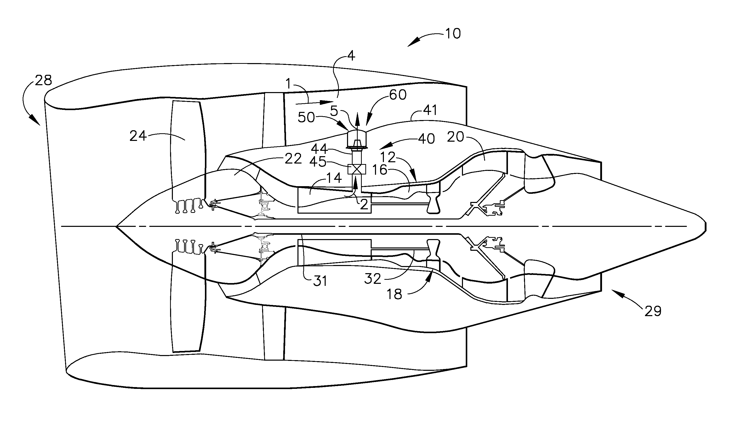
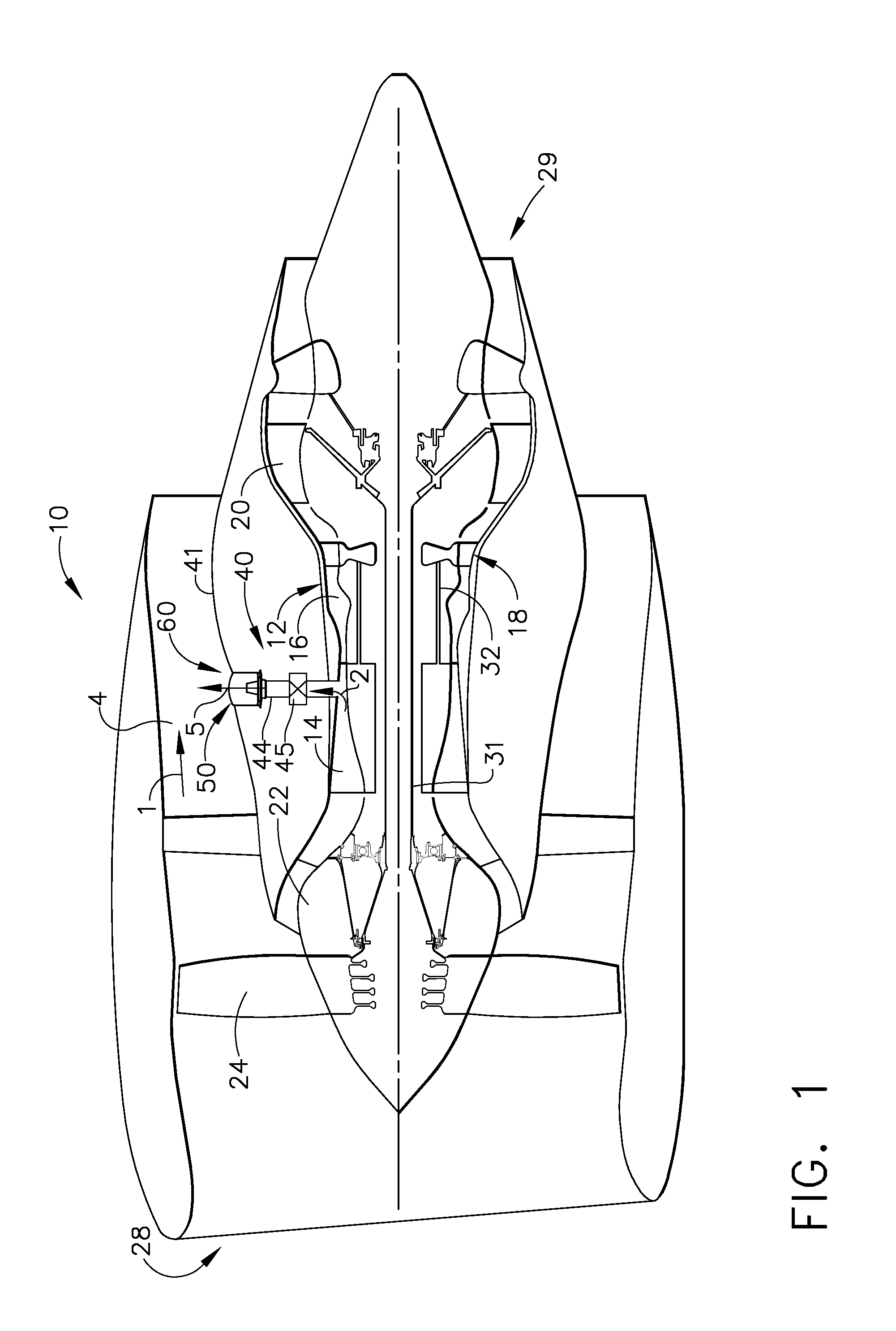
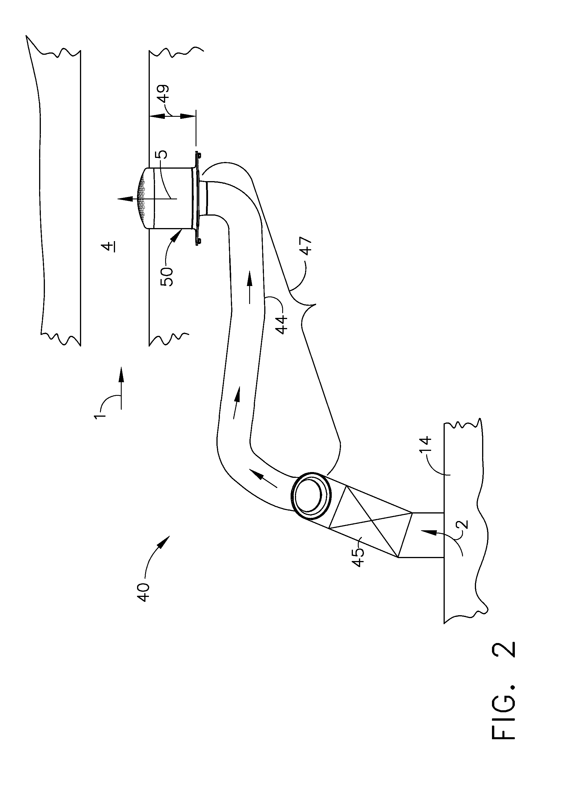
[0018]In the following detailed description, reference is made to the accompanying drawings, which form a part hereof. In the drawings, similar symbols typically identify similar components, unless context dictates otherwise. The illustrative embodiments described in the detailed description, drawings, and claims are not meant to be limiting. Other embodiments may be utilized, and other changes may be made, without departing from the spirit or scope of the subject matter presented here. It will be readily understood that the aspects of the present disclosure, as generally described herein, and illustrated in the figures, can be arranged, substituted, combined, and designed in a wide variety of different configurations, all of which are explicitly contemplated and make part of this disclosure.

[0019]The present disclosure includes, inter alia, muffling systems, and more specifically muffling devices capable of inducing high pressure drops and desirable flow properties.

[0020]The presen...


PUM


Abstract

Compact, high-pressure exhaust muffling devices are disclosed. Some example muffling devices may include an inner flow conditioner including an inlet configured to convey a pressurized fluid flow into an inner flow conditioner interior. The inner flow conditioner may include a plurality of inner flow conditioner holes. The muffling device may include an exhaust can disposed substantially around the inner flow conditioner and arranged to receive the pressurized fluid flow via the inner flow conditioner holes into an exhaust can interior. The exhaust can may include a plurality of exhaust screen holes arranged to discharge the pressurized fluid flow from the exhaust can interior. The exhaust can interior may be substantially devoid of flow obstructions between the plurality of inner flow conditioner holes and the exhaust screen holes.

Description

CROSS REFERENCE TO RELATED APPLICATION[0001]This application claims the benefit of U.S. Provisional Application No. 61 / 580,675, filed Dec. 28, 2011, which is incorporated by reference.BACKGROUND[0002]The subject matter disclosed herein relates generally to muffling systems, and, more specifically, to muffling devices capable of inducing high pressure drops and desirable flow properties.[0003]In a gas turbine engine, air is pressurized in a compression module during operation. The air channeled through the compression module is mixed with fuel in a combustor and ignited, generating hot combustion gases which flow through turbine stages that extract energy therefrom for powering the fan and compressor rotors and generate engine thrust to propel an aircraft in flight or to power a load, such as an electrical generator.[0004]In some gas turbine engines, a portion of the high-pressure air, such as, for example, bleed air from a compressor, may be extracted or bled from the compressor for...

Claims


Application Information

Patent Timeline
Patent Type & Authority Patents(United States)
IPC IPC(8): B64D33/04
CPCF01D25/30F02C6/08F02C7/24F01D17/105F05B2250/191Y02T50/60
Inventor MASON, JEFFREY LEESIEG, DANIEL ALEXANDERGUTIERREZ, CARLOS EDUARDOGLESSNER, JOHN CARLLAWLESS, CHARLES STEVE
Owner GENERAL ELECTRIC CO
Why Eureka
Try Eureka