ESD Protection Device

a protection device and electrostatic discharge technology, applied in the direction of overvoltage protection resistors, emergency protective arrangements for limiting excess voltage/current, arrangements responsive to excess voltage, etc., can solve the problem of damage or malfunction of electronic devices, limited adjustment amount, and difficult to achieve desired responsivity to esd, so as to prevent degradation of discharge characteristics caused by repetitive discharges, the effect of easy adjustment and stabilization

Active Publication Date: 2013-05-07
MURATA MFG CO LTD
View PDF15 Cites 0 Cited by
  • Summary
  • Abstract
  • Description
  • Claims
  • Application Information

AI Technical Summary

Benefits of technology

[0009]To overcome the problems described above, preferred embodiments of the present invention provide an ESD protection device whose ESD characteristics are easily adjusted and stabilized and that prevents the degradation of discharge characteristics caused by repetitive discharges.

Problems solved by technology

ESD causes damage or malfunctioning of electronic devices.
An excessively high voltage, for example, generated by static electricity through an antenna of a mobile phone causes discharge between the discharge electrodes of the ESD protection device, which directs the static electricity to the ground.
However, in such an ESD protection device, the responsivity to ESD varies due to variations in the space between the discharge electrodes.
Furthermore, although the responsivity to ESD needs to be adjusted using an area of the region sandwiched between discharge electrodes facing each other, the amount of adjustment is limited by the size of a product or other factors.
Therefore, it is often difficult to achieve desired responsivity to ESD.
However, in such a structure, the conductive material is scattered due to the shock during discharge and, thus, the distribution density is decreased.

Method used


Image

  • ESD Protection Device
  • ESD Protection Device
  • ESD Protection Device

Examples


Embodiment Construction

[0033]Preferred embodiments of the present invention will now be described with reference to FIGS. 1A to 8B.

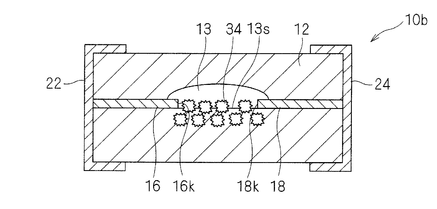
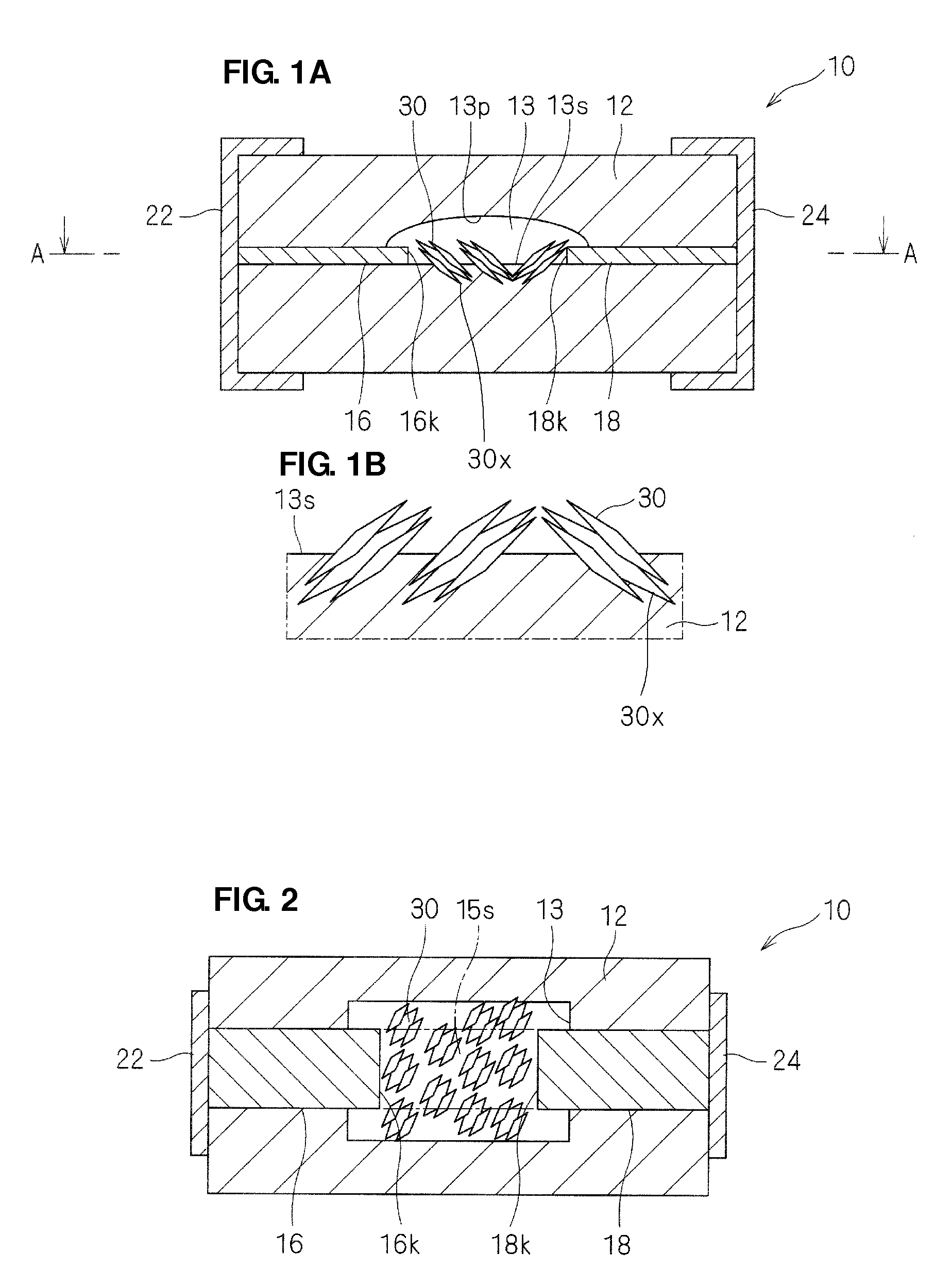
[0034]An ESD protection device 10 according to a first preferred embodiment of the present invention will be described with reference to FIGS. 1A, 1B and 2. FIG. 1A is a sectional view of the ESD protection device 10. FIG. 1B is a sectional view of a principal portion of a cavity 13 included in the ESD protection device 10. FIG. 2 is a sectional view taken along line A-A of FIG. 1A.

[0035]As shown in FIGS. 1A, 1B and 2, the ESD protection device 10 preferably includes a cavity 13 provided in a substrate body 12 of a ceramic multilayer substrate. A pair of discharge electrodes 16 and 18 are arranged such that respective edges 16k and 18k are exposed in the cavity 13. The edges 16k and 18k of the discharge electrodes 16 and 18 are arranged so as to face each other with a space provided therebetween. The discharge electrodes 16 and 18 preferably extend to the outer circumferential...


PUM


Abstract

An ESD protection device is constructed such that its ESD characteristics are easily adjusted and stabilized and degradation of discharge characteristics caused by repetitive discharges is reliably prevented. The ESD protection device includes an insulating substrate, a cavity provided in the insulating substrate, at least a pair of discharge electrodes including exposed portions arranged to face each other and to be exposed in the cavity, external electrodes provided on a surface of the insulating substrate and connected to the discharge electrodes, and a conductive material dispersed along at least a portion of an inner circumferential surface which defines the cavity between the exposed portions of the discharge electrodes, the conductive material including an anchor portion embedded in the insulating substrate.

Description

BACKGROUND OF THE INVENTION[0001]1. Field of the Invention[0002]The present invention relates to an electrostatic discharge (ESD) protection device, and more particularly, to an ESD protection device having improved ESD characteristics and reliability that includes discharge electrodes disposed in a cavity of an insulating substrate and arranged to face each other.[0003]2. Description of the Related Art[0004]ESD is a phenomenon in which strong electrical discharge is generated when a charged conductive body (e.g., human body) comes into contact with or comes sufficiently close to another conductive body (e.g., an electronic device). ESD causes damage or malfunctioning of electronic devices. To prevent this, it is necessary to prevent an excessively high voltage generated during discharge from being transmitted to circuits of electronic devices. ESD protection devices, which are also called surge absorbers, are used for such an application.[0005]An ESD protection device is disposed, ...

Claims


Application Information

Patent Timeline
Patent Type & Authority Patents(United States)
IPC IPC(8): H01C7/12H02H3/22
CPCH01T4/12
Inventor YAMAMOTO, ISSEIADACHI, JUNKAMADA, AKIHIKO
Owner MURATA MFG CO LTD
Why Eureka
Try Eureka