Portable campfire chimney

a campfire and chimney technology, applied in the field of portable campfire chimneys, can solve the problems of many people being injured from burns, and still a potential for burn injuries

Active Publication Date: 2013-05-21
LITZENBERGER BRAD
View PDF10 Cites 5 Cited by
  • Summary
  • Abstract
  • Description
  • Claims
  • Application Information

AI Technical Summary

Problems solved by technology

However, they have hazards and many people are injured from burns due to proximity to the open fire, smoke and flying embers.
As well, a door is provided for access to an interior camping grill and so there is still a potential for burn injuries.

Method used


Image

  • Portable campfire chimney
  • Portable campfire chimney
  • Portable campfire chimney

Examples


Embodiment Construction

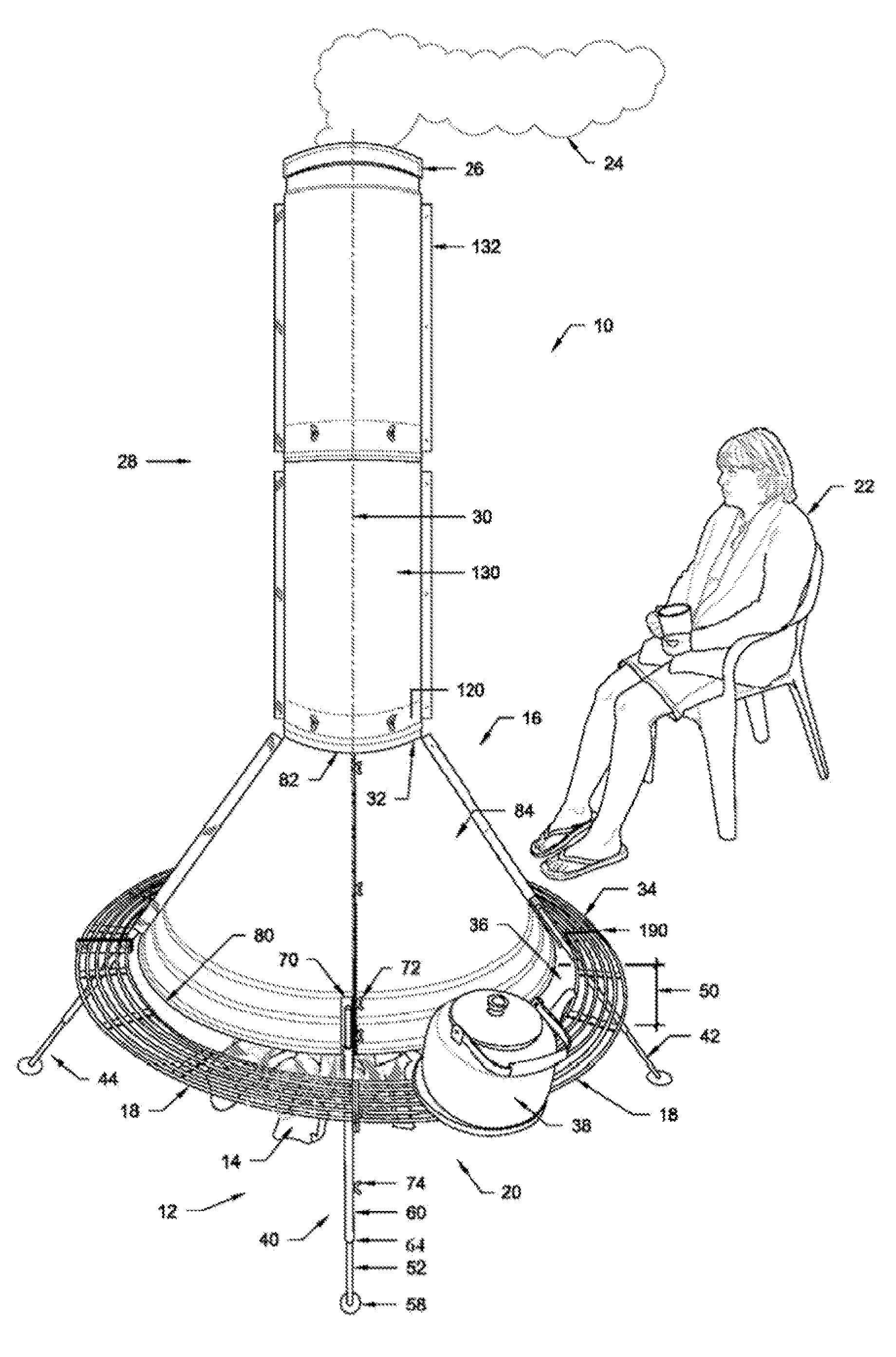
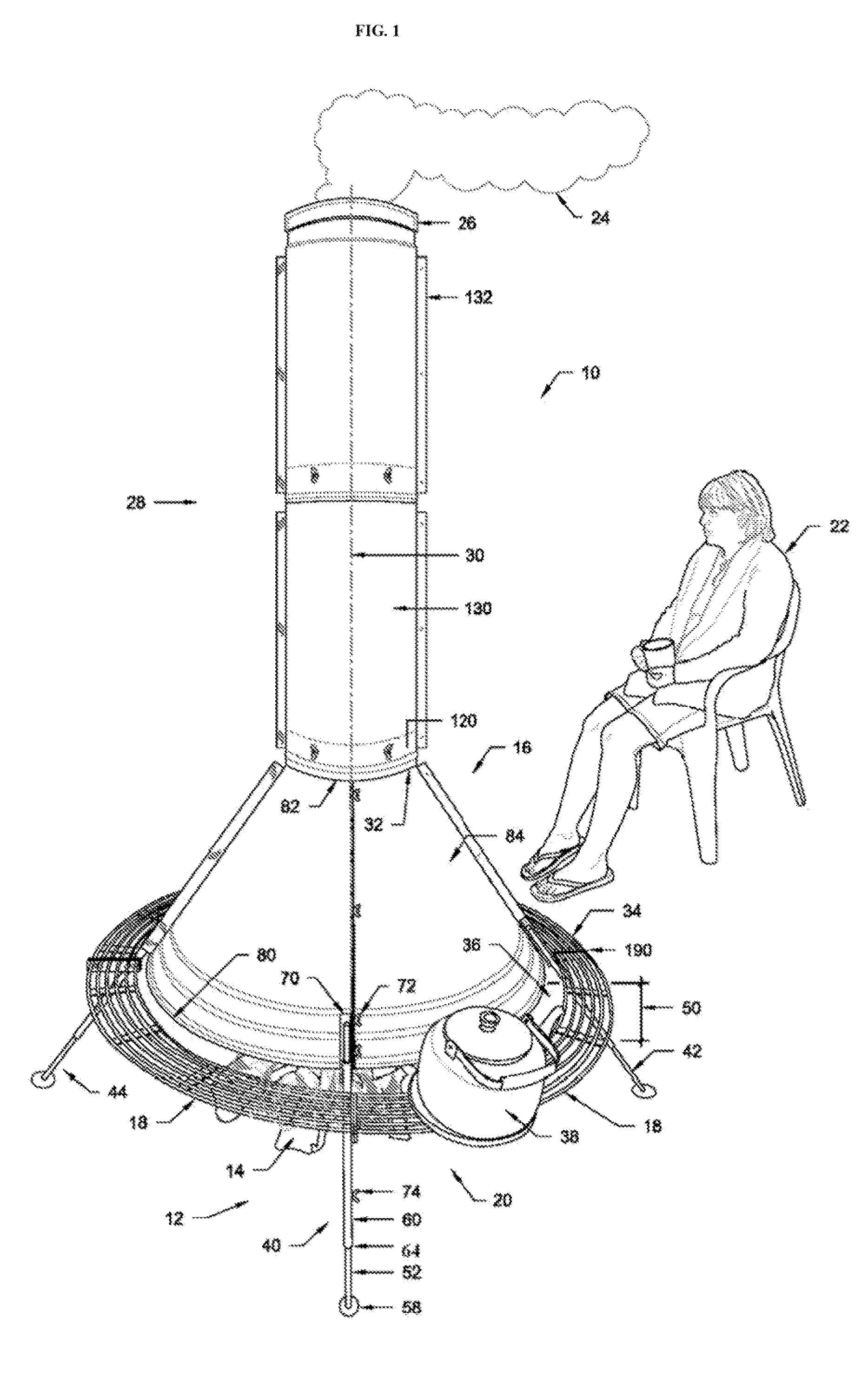
[0020]Referring to FIG. 1, there is shown one embodiment of my invention 10 which is a portable campfire chimney. The chimney comprises base means 12 for supporting the portable chimney 10 over a campfire 14.

[0021]The invention may be constructed from light weight sheet metal of a suitable gauge.

[0022]The chimney 10 further comprises a first body 16 disposed over the base means 12 and centered above the campfire for creating a draft 18 at the bottom end 20 of the chimney and shielding adjacent persons 22 from combustion products 24 of the campfire 14 which are exhausted from the top end 26 of the chimney.

[0023]A second body 28 is disposed axially 30 on the top end 32 of the first body 16 for collecting combustion products 24 from the first body and exhausting them to the atmosphere by way of the top end 26 of the chimney.

[0024]In the embodiment shown, there is included an exterior ring-grill 34 disposed radially around the first body 16 and spaced 36 away from the first body for pla...


PUM


Abstract

A campfire chimney for placement over a campfire to shield nearby persons from excessive heat, smoke and burning embers. The campfire has a base comprising at least for telescoping legs to adjust the height of the chimney over the fire. The chimney has a bottom conical section for placement over the fire and a tubular top section for exhausting products of combustion. The chimney can be disassembled and can be transported conveniently by a single individual.

Description

FIELD OF THE INVENTION[0001]This invention relates to stoves and furnaces as well as ventilation means and particularly to a portable campfire chimney.BACKGROUND OF THE INVENTION[0002]Outdoor campfires are a North American ritual. However, they have hazards and many people are injured from burns due to proximity to the open fire, smoke and flying embers. As well, outdoor campfires are a well known source of forest fires. There have been many attempts at manufacturing devices that can form a barrier between people and the hazardous aspects of an outdoor fire while still providing the enjoyment from the visual, cooking and heating aspects of an outdoor fire. One such attempt is embodied in U.S. Pat. No. 4,875,462 CAMPFIRE SMOKESTACK by Armstrong et al. issued on Oct. 24, 1989. This patent discloses a plurality of nesting, hollow frustums stacked one-upon-the-other to form a conical smokestack. This patent sits low to the fire and obscures the blaze which is an enjoyable component of t...

Claims


Application Information

Patent Timeline
Patent Type & Authority Patents(United States)
IPC IPC(8): F24B3/00
CPCF23J11/08F24B1/181
Inventor LITZENBERGER, BRAD
Owner LITZENBERGER BRAD
Why Eureka
Try Eureka