Holographic reconstruction system and method with an enlarged visibility region

a reconstruction system and visibility technology, applied in the field of holographic reconstruction system with an enlarged visibility region, can solve the problems of disappearance of visibility, difficult to find the borders of the reconstruction space for an observer whose eyes, and difficulty in finding the visibility of the three-dimensional reconstruction

Inactive Publication Date: 2013-05-21
SEEREAL TECHNOLOGIES
View PDF8 Cites 2 Cited by
  • Summary
  • Abstract
  • Description
  • Claims
  • Application Information

AI Technical Summary

Benefits of technology

[0011]It is therefore the object of the present invention to provide a holographic reconstruction system which allows one or multiple observers to watch the reconstructed scene from various positions, and which can be realised in a simple manner using conventional means.
[0017]In a preferred embodiment of the solution according to this invention, a laser light source is used as the light source means. It is further preferred that the light source means periodically provide light pulses at a certain switching frequency. The light source means can for example have the form of a pulsed laser. In order to control the switching frequency, the reconstruction system can further comprise light source control means. In another embodiment, the holographic reconstruction system further comprises deflection drive control means for controlling the rotary frequency of the deflection drive means. Switching frequency and rotary frequency preferably have a certain ratio. In a special embodiment, switching frequency and rotary frequency can correspond such that the light source means deliver up to one light pulse within a displacement distance which corresponds to the extent of the visibility region in the direction of displacement. Switching frequency and / or rotary frequency can therein be controlled. Thanks to this design, it can be avoided that the observer perceives multiple perspectives while the visibility region passes his eye. This way, a blurred perception of the scene can be prevented.
[0021]The deflection means are preferably a mirror, in particular a front surface mirror. The deflection means can further be planar mirrors or can have a spherical or aspherical effect. Thanks to the spherical or aspherical effect, additional optical effects can be achieved. It is for example possible to integrate additional components of the holographic reconstruction system into the deflection means.
[0024]In another embodiment, the holographic reconstruction system comprises eye position detection means for detecting the position of at least one observer eye. The light source means can then provide light depending on the detected position of the observer eye. For example, light pulses could be provided only in a region in front of, at or behind an eye position, seen in the direction of displacement of the visibility region. Moreover, the reconstruction means can then preferably compute the scene to be holographically reconstructed depending on the detected position of the observer eye. It is for example possible to compute a hologram only for the detected eye position. Or, in a further embodiment, a hologram is computed for a position of the visibility region which lies in front of the eye position, seen in the direction of displacement of the visibility region, and for the subsequent position(s) of the visibility region. This way, the computational load required for providing the hologram can be reduced and light energy can be saved.

Problems solved by technology

However, this may lead to problems with the visibility of the three-dimensional reconstruction, if the observer eye is only partly situated inside the visibility region.
Already a slight movement of the observer may cause effects such as disappearance of visibility, vignetting or distortion of the spatial frequency spectrum.
Moreover, the borders of the reconstruction space are difficult to find for an observer whose eyes are situated outside the visibility region.
This causes the deflection unit to move intermittently, which is difficult to be realised using conventional means, in particular at high frequencies, e.g. higher than 20 Hz.
Again, this is difficult to be realised using conventional means.

Method used


Image

  • Holographic reconstruction system and method with an enlarged visibility region
  • Holographic reconstruction system and method with an enlarged visibility region
  • Holographic reconstruction system and method with an enlarged visibility region

Examples


Embodiment Construction

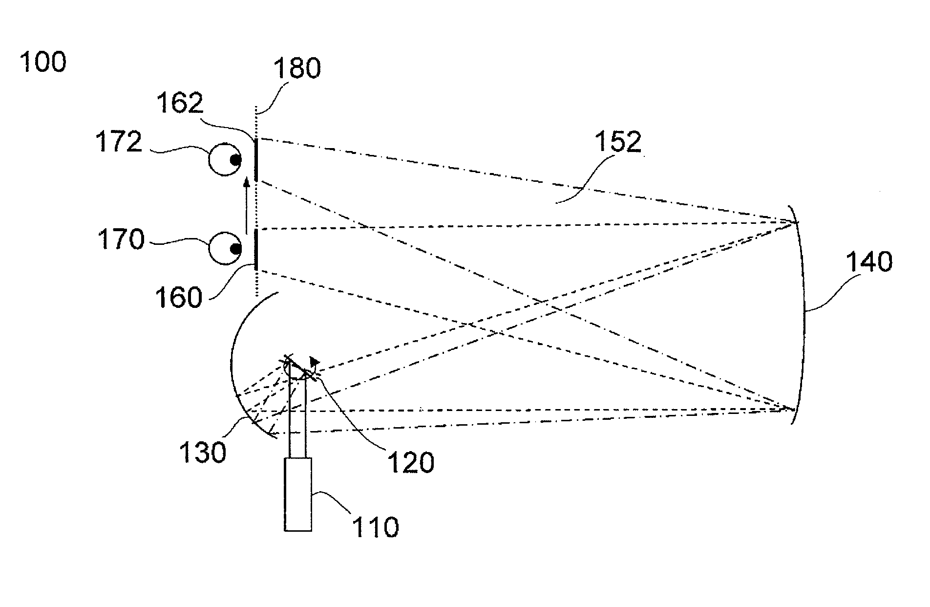
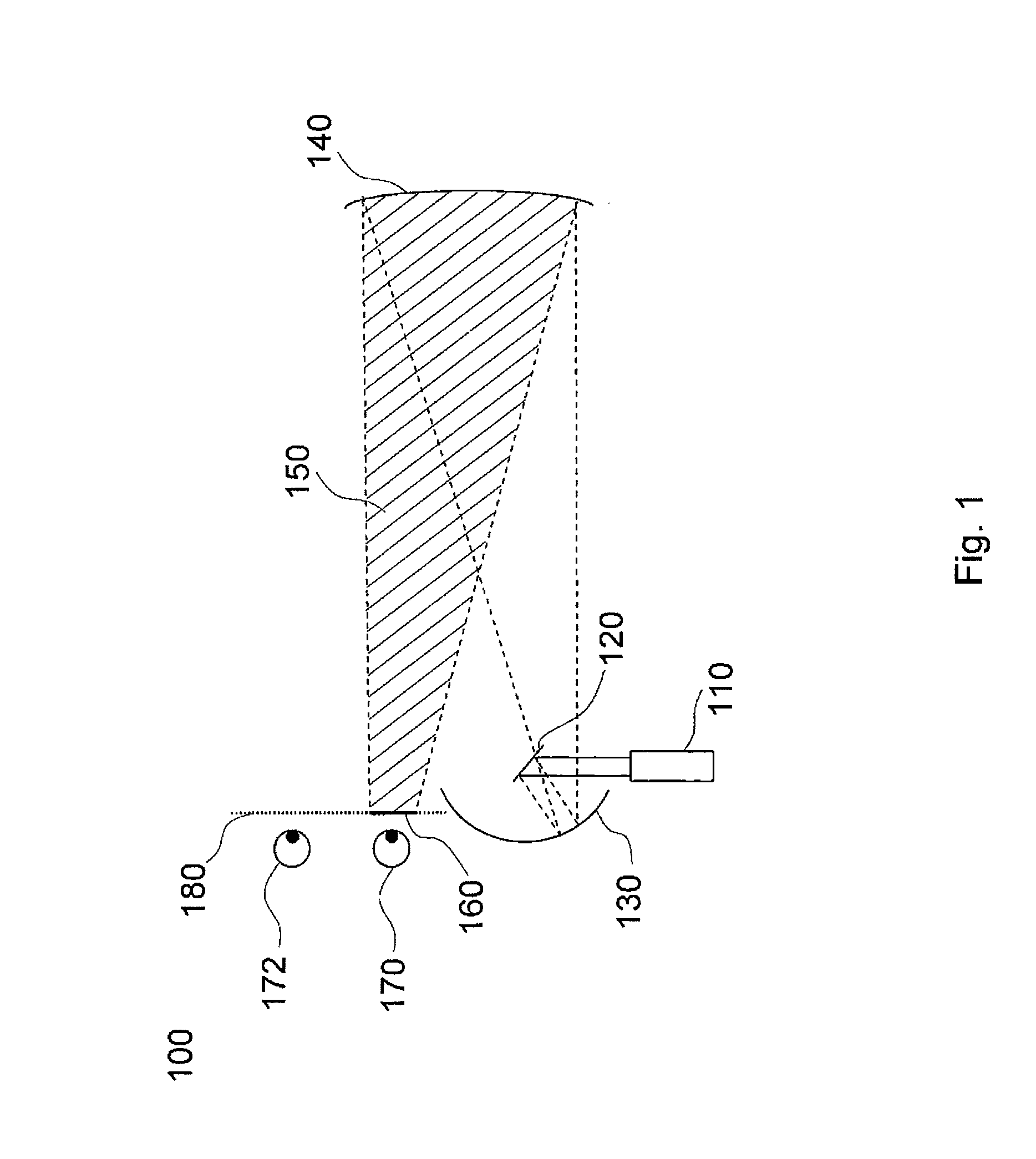
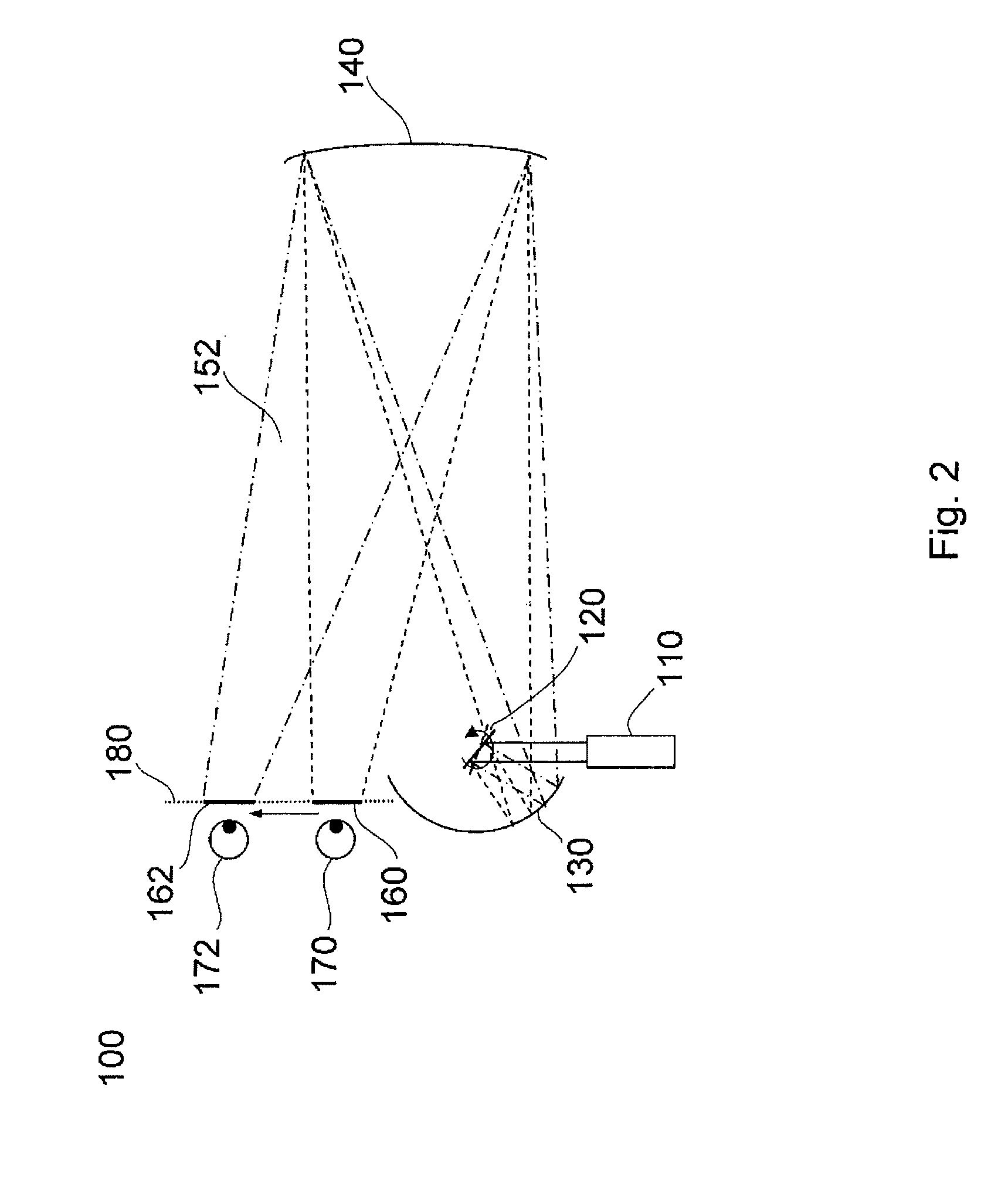
[0033]FIG. 1 is a top view which shows in a simplified diagram the principle of, the present invention. The position of the visibility region at a first point of time is shown.

[0034]The shown holographic reconstruction system 100 comprises first optical means 110, deflection means 120, projection means 130, and a display screen 140. The drawing further shows a reconstruction space 150 which stretches between display screen 140 and a visibility region 160, a first eye position 170, a second eye position 172, and an enlarged visibility region 180.

[0035]The first optical means 110 here comprise a hologram projector, which projects an intermediate image of a hologram, which is encoded on a spatial light modulator (SLM) (not shown in this drawing), onto the deflection means. The first optical means 110 are disposed in front of the deflection means 120 in the optical path.

[0036]The deflection means 120, for example a plane mirror, change the direction of the image of the SLM, which is pro...


PUM


Abstract

A holographic reconstruction system and a corresponding holographic reconstruction method are disclosed. The holographic reconstruction system comprises light source means for providing substantially coherent light, reconstruction means for holographically reconstructing a scene and for producing a visibility region from where the viewer can view the holographically reconstructed scene, and deflection means for positioning the visibility region. The aim of the invention is to improve the visibility region of a holographic reconstruction system. To achieve this aim, the holographic reconstruction system comprises deflection drive means for continuously rotating or pivoting the deflection means about a rotational axis at a rotary frequency, thereby displacing the visibility region. The invention allows one or more viewers to view the scene reconstructed by means of the holographic reconstruction system from different positions while facilitating the implementation of the holographic reconstruction system with conventional means.

Description

CROSS REFERENCE TO RELATED APPLICATIONS[0001]This application claims the priority of PCT / EP2008 / 055891, filed on May 14, 2008, which claims priority to German Application No. 10 2007 024235.4, filed May 21, 2007, the entire contents of which are hereby incorporated in total by reference.BACKGROUND OF THE INVENTION[0002]The present invention relates to a holographic reconstruction system with an enlarged visibility region, and to an according method. The holographic reconstruction system comprises light source means for providing substantially coherent light, reconstruction means for the holographic reconstruction of a scene and for generating a visibility region from which an observer can watch the holographically reconstructed scene, and deflection means for positioning the visibility region.[0003]In a holographic reconstruction system, sufficiently coherent light is modulated by spatial light modulator means (SLM), e.g. a liquid crystal display (LCD). A diffractive structure, the ...

Claims


Application Information

Patent Timeline
Patent Type & Authority Patents(United States)
IPC IPC(8): G03H1/08
CPCG03H1/2205G03H1/2294G03H2226/05G03H2001/2292G03H2223/24G03H2001/2242G03H2001/221G03H2001/2239
Inventor BUSCHBECK, STEFFEN
Owner SEEREAL TECHNOLOGIES
Why Eureka
Try Eureka