
Tiled display device having a plurality of display panels

a technology of display panel and display panel, which is applied in the direction of identification means, instruments, computing, etc., can solve problems such as alignment errors between display panels

Active Publication Date: 2022-07-14
SAMSUNG DISPLAY CO LTD
View PDF47 Cites 0 Cited by
  • Summary
  • Abstract
  • Description
  • Claims
  • Application Information

AI Technical Summary

Benefits of technology

[0005]Embodiments of the invention provide a tiled display device capable of preventing a boundary line between a plurality of display panels from being perceived.
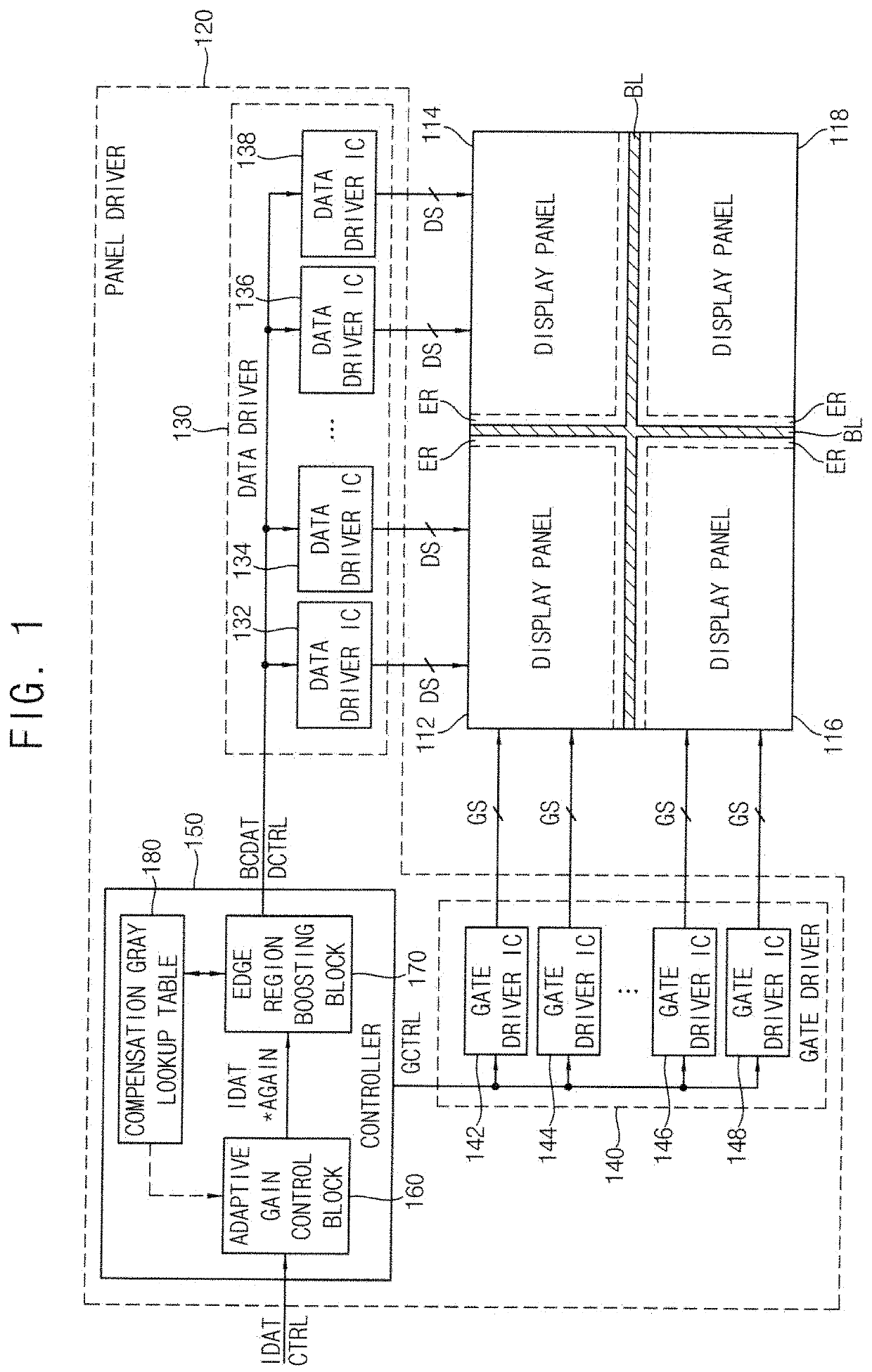
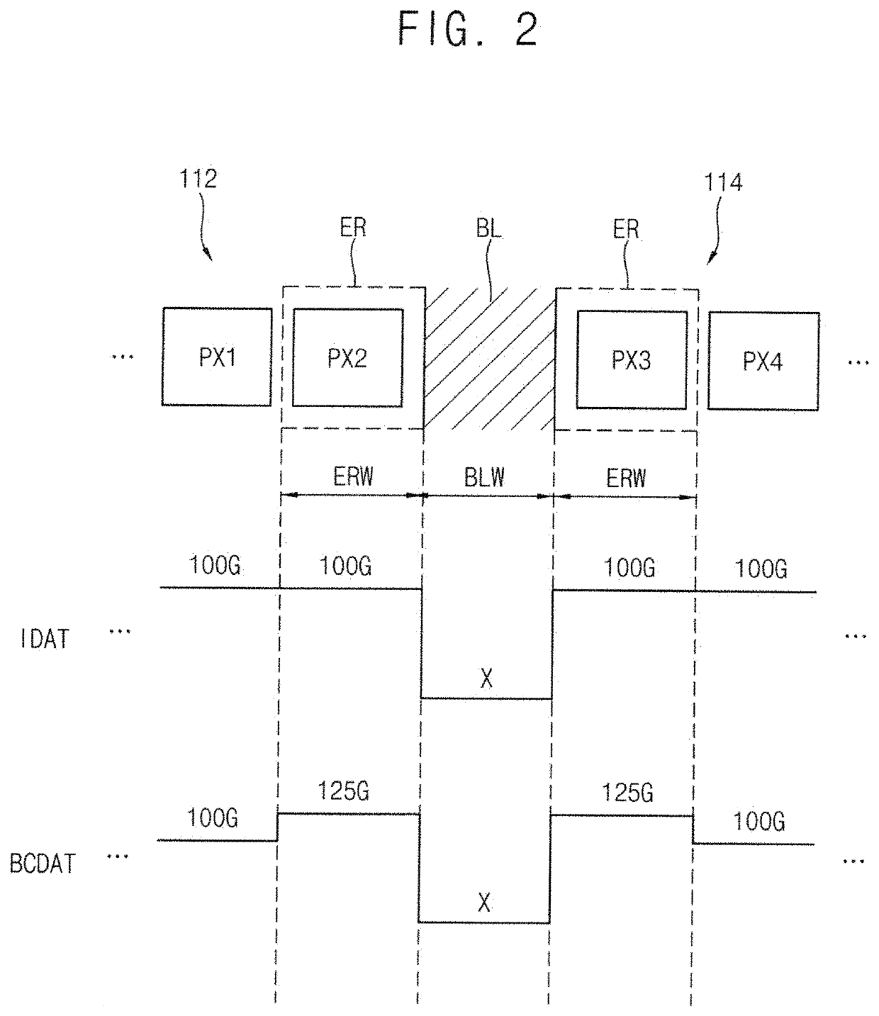
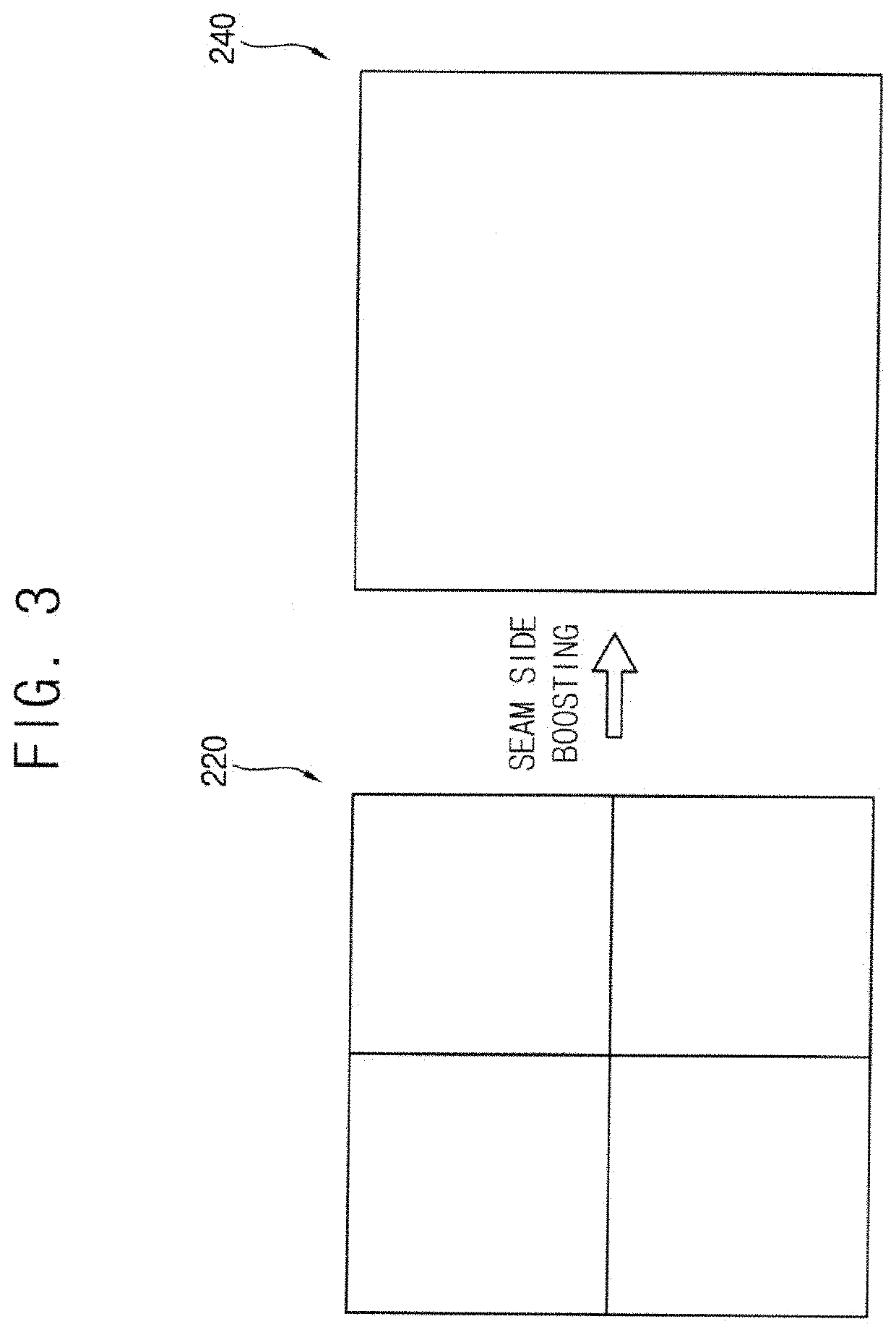
[0026]In embodiments of the invention, As described herein, a tiled display device may multiply input gray levels of input image data for a plurality of display panels coupled to each other by an adaptive gain, may generate boundary compensated image data by adding boundary compensation gray levels to the input gray levels (multiplied by the adaptive gain) for an edge region adjacent to a boundary line between the plurality of display panels, and may drive the plurality of display panels based on the boundary compensated image data. In such embodiments, the adaptive gain may be gradually decreased over a plurality of frame periods in a case where a sum of each of the input gray levels for the edge region and a corresponding one of the boundary compensation gray levels exceeds a maximum gray level. Accordingly, in such embodiments of the tiled display device, the boundary line between the plurality of display panels may be effectively prevented from being perceived.

Problems solved by technology

In a tiled display device where a scattering lens is disposed on a boundary line between a plurality of display panels therein to prevent the boundary line from being perceived, an image may be blurred in a region adjacent to the scattering lens, and an alignment error between the display panels may occur.

Method used


Image

  • Tiled display device having a plurality of display panels
  • Tiled display device having a plurality of display panels
  • Tiled display device having a plurality of display panels

Examples


Embodiment Construction

[0042]The invention now will be described more fully hereinafter with reference to the accompanying drawings, in which various embodiments are shown. This invention may, however, be embodied in many different forms, and should not be construed as limited to the embodiments set forth herein. Rather, these embodiments are provided so that this disclosure will be thorough and complete, and will fully convey the scope of the invention to those skilled in the art. Like reference numerals refer to like elements throughout.

[0043]It will be understood that when an element is referred to as being “on” another element, it can be directly on the other element or intervening elements may be present therebetween. In contrast, when an element is referred to as being “directly on” another element, there are no intervening elements present.

[0044]It will be understood that, although the terms “first,”“second,”“third” etc. may be used herein to describe various elements, components, regions, layers a...


PUM


Abstract

A tiled display device includes a plurality of display panels coupled to each other, where each of the plurality of display panels includes an edge region adjacent to a boundary line between the plurality of display panels, and a panel driver which multiplies input gray levels of input image data for the plurality of display panels by an adaptive gain, generates boundary compensated image data by adding boundary compensation gray levels to the input gray levels multiplied by the adaptive gain for the edge region, and drives the plurality of display panels based on the boundary compensated image data. The adaptive gain is gradually decreased over a plurality of frame periods in a case where a sum of each of the input gray levels for the edge region and a corresponding one of the boundary compensation gray levels exceeds a maximum gray level.

Description

[0001]This application claims priority to Korean Patent Application No. 10-2021-0002570, filed on Jan. 8, 2021, and all the benefits accruing therefrom under 35 U.S.C. § 119, the content of which in its entirety is herein incorporated by reference.BACKGROUND1. Field[0002]Embodiments of the invention relate to a display device, and more particularly to a tiled display device including a plurality of display panels coupled to each other.2. Description of the Related Art[0003]To overcome a resolution limitation and a size limitation of a single display panel, a tiled display device implemented by coupling a plurality of display panels has been developed. In such a tiled display device, a boundary line (or a seam line) between the plurality of display panels may be viewed or perceived by a user. Accordingly, a tiled display device where a scattering lens is disposed on the boundary line to prevent the boundary line from being perceived has been developed.SUMMARY[0004]In a tiled display ...

Claims


Application Information

Patent Timeline
Patent Type & Authority Applications(United States)
IPC IPC(8): G09G3/34G09G3/00
CPCG09G3/3406G09G3/006G09G2360/16G09G2320/0673G09G2320/0233G09G2310/027G09G3/3648G09G3/3225G09F9/35G09F9/33G09G3/20G09G2300/026G09G2310/0232G09G2360/145G09G2320/0693G09G2320/0247G09G2320/0271G09G2320/0285G09F9/3023H10K59/18G06F3/1446G09G3/2007G09G3/2096G09G2320/0686G09G2360/04
Inventor YOO, HYUNSEUKYOU, BONGHYUNKIM, KYUNG-WOOHONG, SEOKHA
Owner SAMSUNG DISPLAY CO LTD
Learn More