
Lighting device including adjustable cover

a technology of light-emitting devices and covers, which is applied in the direction of semiconductor devices, light-emitting devices, fixed installations, etc., can solve the problems that the light-emitting device is still limited in application and the lighting application cannot be utilized in its full potential, and achieve the effect of preventing glar

Active Publication Date: 2021-10-19
SIGNIFY HLDG BV
View PDF20 Cites 0 Cited by
  • Summary
  • Abstract
  • Description
  • Claims
  • Application Information

AI Technical Summary

Benefits of technology

This invention is a lighting device that aims to prevent glare and control the lighting effect. It consists of an elongated carrier that is placed on a surface and has a light source on its sides. Additionally, there is an adjustable cover that is positioned on the opposite side of the carrier, facing the surface. This cover can be moved relative to the carrier to adjust the lighting effect. The light source used is an LED light source. The technical effect of this invention is the prevention of glare caused by the lighting device and the control of the lighting effect.

Problems solved by technology

Although dazzle is somewhat prevented, it is a disadvantage that such lighting device is still limited in application to prevent further dazzle or glare.
US2012 / 0002409 A1 comprises a mount with multiple functionalities, of which at least one is a lighting functionality, a disadvantage of such a mount remains that the lighting application cannot be utilized in its full potential.

Method used


Image

  • Lighting device including adjustable cover
  • Lighting device including adjustable cover
  • Lighting device including adjustable cover

Examples


Embodiment Construction

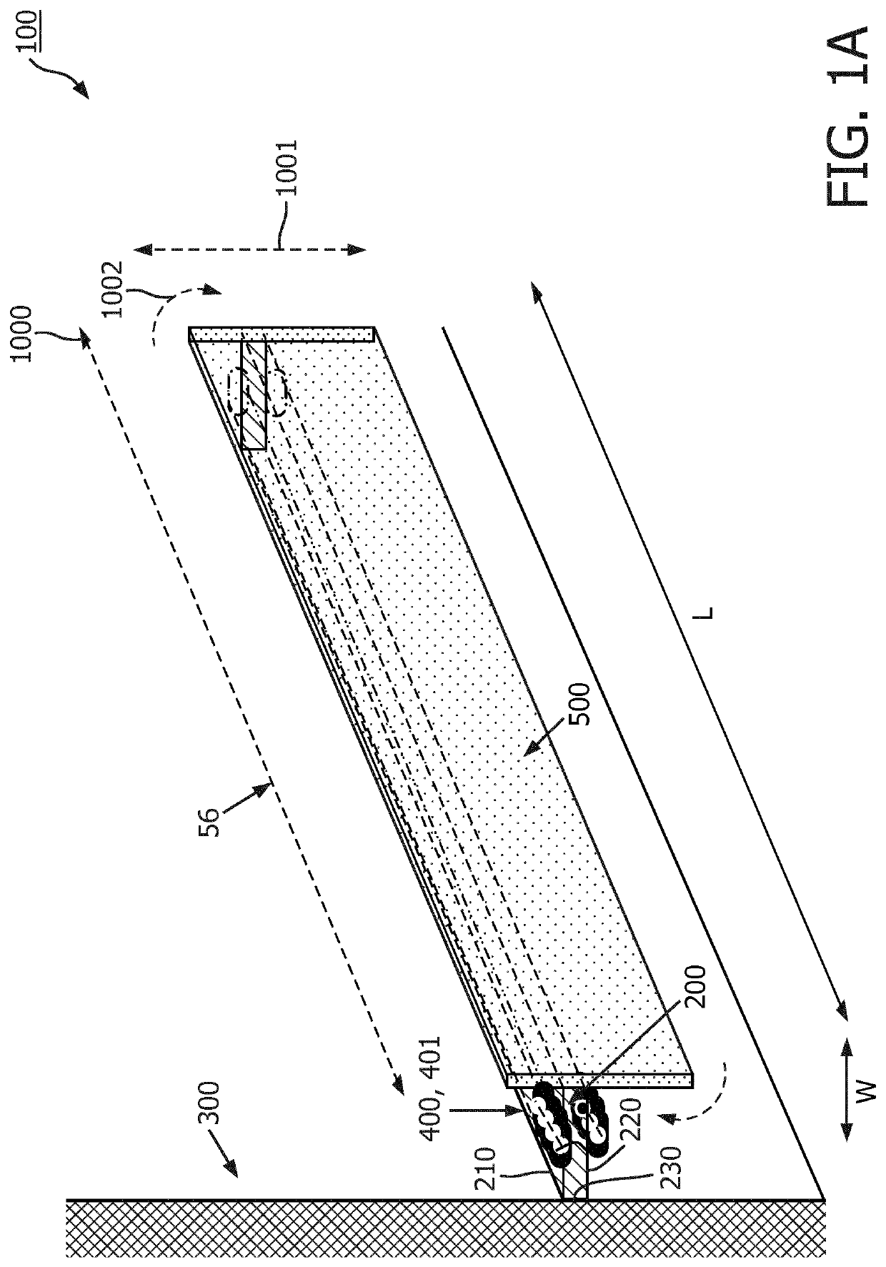
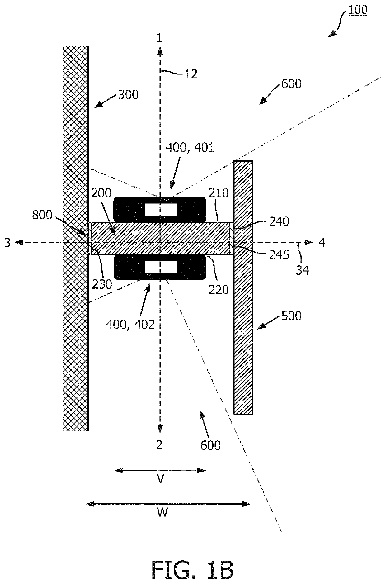
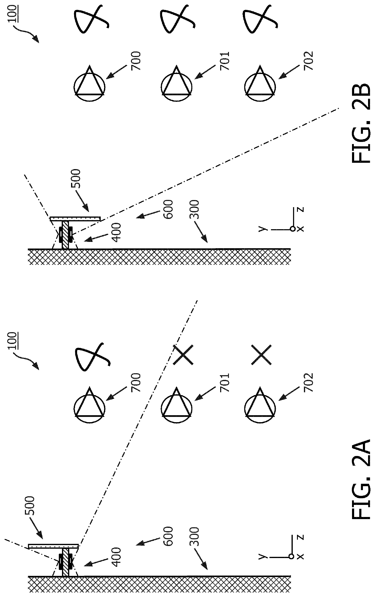
[0048]FIGS. 1A and 1B depict schematically, by non-limiting example, an embodiment of a lighting device 100 comprising a surface-mountable elongated carrier 200 for positioning relative to a surface 300, at least one light source 400, and an adjustable cover 500. Said embodiment is depicted in perspective in figure lA and in a side view in FIG. 1B.

[0049]Referring to the embodiment disclosed in FIG. 1A-B, the surface-mountable elongated carrier 200 is a rectangular profile mounted to the surface 300. The rectangular profile is a single extruded piece with an I shape. Alternatively, the elongated carrier is injected molded. Alternatively, the surface-mountable elongated carrier 200 may have another fixed profile shape, which is extruded uniformly in the elongated direction (56), like for example a I profile, L-shaped profile, V-shaped profile, round or elliptical. The surface-mountable elongated carrier 200 may also be a hollow profile shape comprising a cavity, which for example may ...


PUM

PropertyMeasurementUnit
distanceaaaaaaaaaa
densityaaaaaaaaaa
widthaaaaaaaaaa

Abstract

The invention provides a lighting device (100) comprising a surface-mountable elongated carrier (200) for positioning relative to a surface (300), at least one light source (400), and an adjustable cover (500); wherein the elongated carrier (200) comprises opposite to each other a first face (210) on a first side and a second face (220) on a second side, the at least one light source (400) is located on the first (210) and second face (220); and 5 wherein the elongated carrier (200) comprises a third face (230) on a third side for facing the surface (300) in mounted position; and wherein the adjustable cover (500) is in connection with the carrier (200) and is positioned on a fourth side of the carrier (200) opposite to the third side, and wherein the adjustable cover (500) is movable relative to the elongated carrier (200) for controlling a light effect (600) originating from the at least one light source (400) 10 wherein the at least one light source (400) comprises a LED light source.

Description

CROSS-REFERENCE TO PRIOR APPLICATIONS[0001]This application is the U.S. National Phase application under 35 U.S.C. § 371 of International Application No. PCT / EP2017 / 062265, filed on May 22, 2017, which claims the benefit of European Patent Application No. 16173665.7, filed on Jun. 9, 2016. These applications are hereby incorporated by reference herein.FIELD OF THE INVENTION[0002]The invention relates to a lighting device comprising a carrier for positioning relative to a surface and at least one light source, and to a system comprising the lighting device and a control unit.BACKGROUND TO THE INVENTION[0003]Such lighting device is known for example from US2012 / 0002409 A1 which discloses a mount having at least one semiconductor light source, where the mount has an elongated basic form and is designed to include at least two functionalities. Of which at least one is a lighting functionality. To implement the at least one lighting functionality, the mount includes at least one semicond...

Claims


Application Information

Patent Timeline
Patent Type & Authority Patents(United States)
IPC IPC(8): F21V14/08F21S6/00F21S8/00F21S4/28F21Y103/00F21Y115/10F21Y107/90
CPCF21V14/08F21S4/28F21S6/005F21S8/033F21Y2103/00F21Y2107/90F21Y2115/10
Inventor BERGMAN, ANTHONIE HENDRIKDEKKER, TIMVAN GHELUWE, JOCHEN RENAATVAN DE SLUIS, BARTEL MARINUS
Owner SIGNIFY HLDG BV
Learn More