
Method for Producing At Least One Solid-Body Layer on a Support That Can Rotate About an Axis of Rotation

Pending Publication Date: 2022-06-30
DP POLAR GMBH
View PDF0 Cites 0 Cited by
  • Summary
  • Abstract
  • Description
  • Claims
  • Application Information

AI Technical Summary

Benefits of technology

The patent describes a method for printing 2D and 3D objects using a laser or UV light to solidify liquid or powder-form material. The method ensures that individual lines of the material are perceived as separate lines, rather than V shapes or multiple lines. The method also allows for the rapid and interruption-free application of multiple material layers to create 3D objects. The technical effects of this method include improved print quality and faster printing times.

Problems solved by technology

The method has the disadvantage that time is needed for stopping and accelerating the print-head module with its accessories at the edges of the support, and this time cannot be used for printing.
This stopping and acceleration can take up as much as 50% of the total printing time in the case of smaller to medium-size printed surfaces, and therefore can significantly reduce the productivity of the method.
Furthermore, the heavy print head and the relatively large and heavy parts connected with it, such as the reservoir with the supply of material capable of flow contained in it, the cable carriers, which are susceptible to wear, and the fixation device must be stopped after every completion of a material layer, and—if a further material layer is supposed to be applied—accelerated in the opposite direction.
The mechanical parts of the positioning devices are subjected to stress as the result of the acceleration forces that occur in this connection, and this leads to corresponding wear of the bearings and guides of the positioning devices, and thereby impairs the precision of the printer.

Method used


Image

  • Method for Producing At Least One Solid-Body Layer on a Support That Can Rotate About an Axis of Rotation
  • Method for Producing At Least One Solid-Body Layer on a Support That Can Rotate About an Axis of Rotation
  • Method for Producing At Least One Solid-Body Layer on a Support That Can Rotate About an Axis of Rotation

Examples


Embodiment Construction

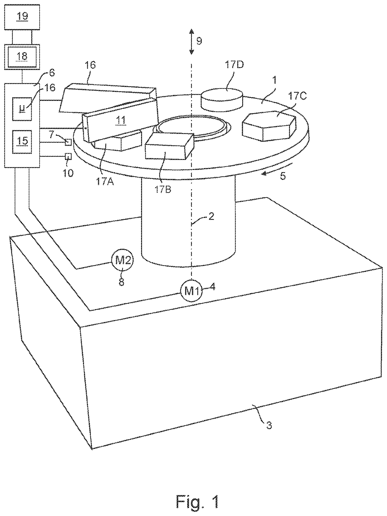
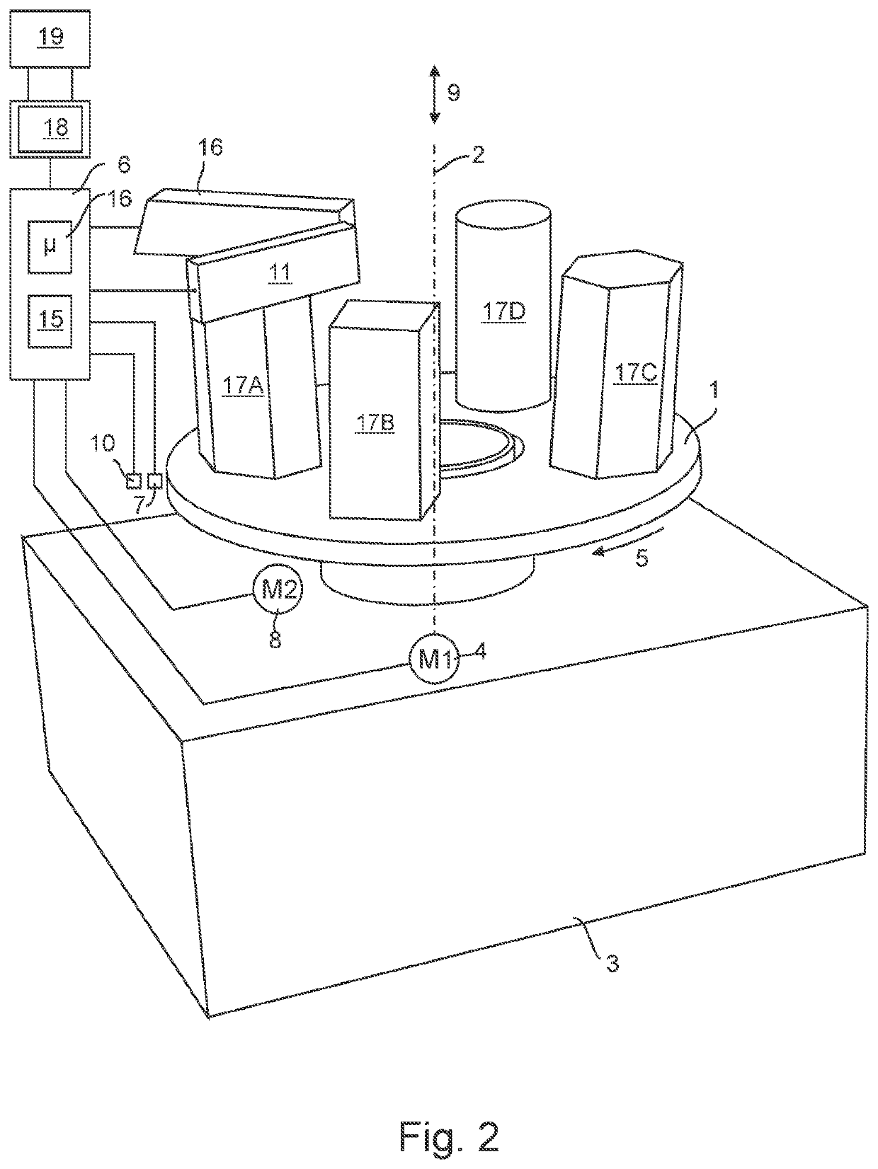
[0077]In the case of a method for layer-by-layer production of a solid-body shaped object on a support 1 that can be rotated about an axis of rotation 2, in accordance with predetermined geometry data, a rotary disk in the shape of a circular ring, which has the support 1, is provided, which disk is mounted so that it can be rotated about a vertical axis of rotation 2, on a holder 3 that is fixed in place (FIGS. 1 and 2). The holder 3 has a standing surface on its underside, by means of which it can be set up on a tabletop or on the floor of a room, for example.

[0078]The support 1 stands in a drive connection with a first positioning device that has a first drive motor 4, by means of which the support 1 can be driven to rotate in the direction of the arrow 5 and can be positioned in accordance with a rotational position reference value signal that is provided by a control device 6. For this purpose, the first drive motor 5 is connected with a first position regulator integrated into...


PUM

PropertyMeasurementUnit
Fractionaaaaaaaaaa
Fractionaaaaaaaaaa
Thicknessaaaaaaaaaa

Abstract

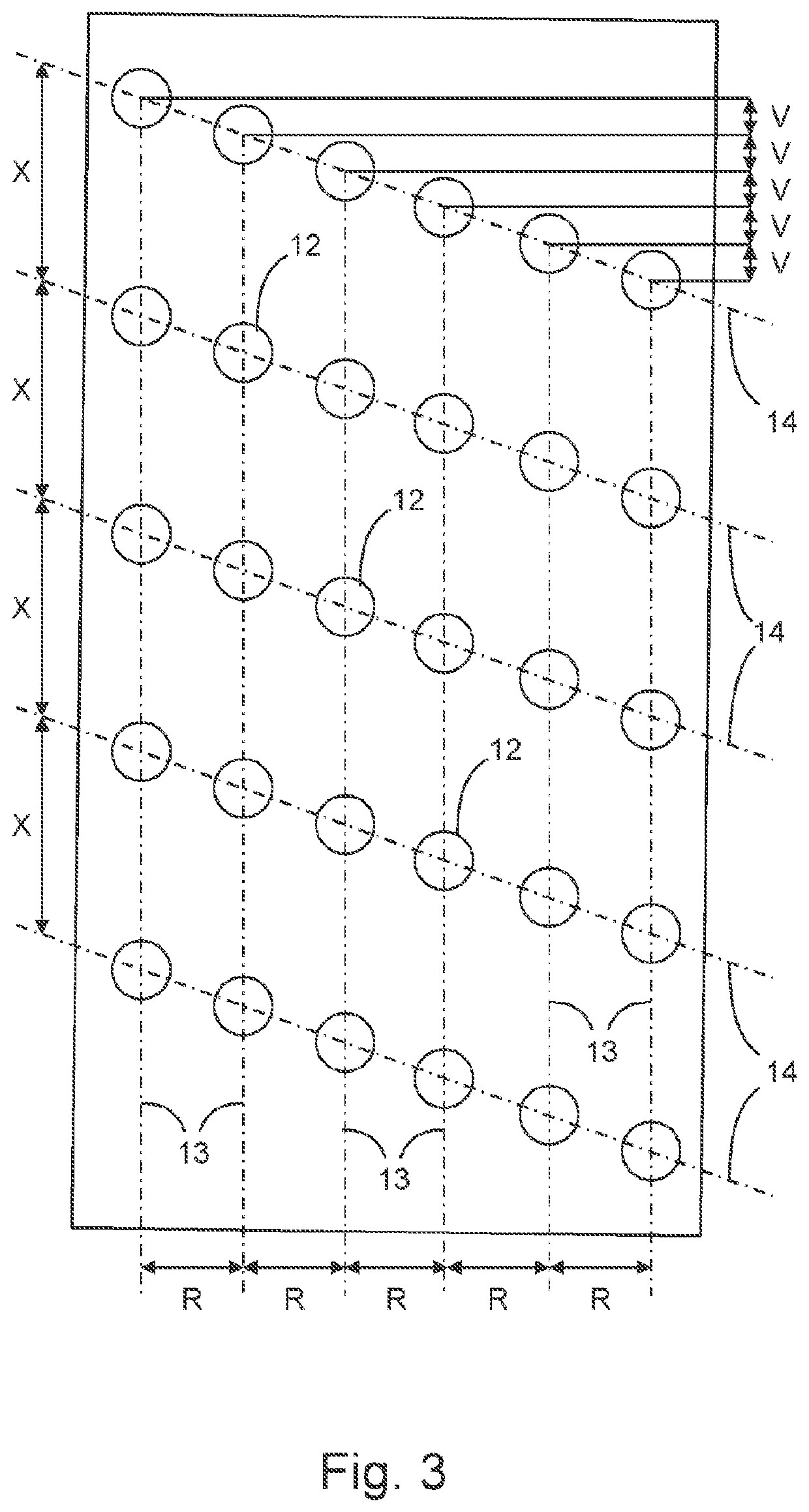
In a method for producing at least one solid-body layer on a support that can be rotated about an axis of rotation, in accordance with predetermined geometry data, an emitter array having a plurality of emitters configured as material-dispensing nozzles is provided, which nozzles are arranged in emitter columns and emitter rows. Emitter columns that are adjacent to one another in the circumferential direction of an axis of rotation are offset from one another, in the expanse direction of the emitter columns, in each instance, in such a manner that the emitters are arranged at different radial distances DA(i) from the axis of rotation. It holds true that: DA(i) DA(i+1). Print dots are assigned to the geometry data, which dots are offset from one another, in a matrix having multiple rows that run next to one another, in such a manner that it holds true that: PA(j)>PA(j+1), wherein PA(j) is the radial distance of the jth print dot Pj of the row in question from the axis of rotation. For print dots Pk for which material is supposed to be dispensed onto the support, at least one material portion, in each instance, is dispensed from the emitter Dk of the emitter array assigned to the print dot Pk in question. Dispensing of the material portions takes place in print cycles in which the emitter array is triggered to dispense material once, in each instance, at a trigger point assigned to the print cycle in question, in each instance, and the support as well as the emitter array are offset relative to one another, from print cycle to print cycle, in each instance, by an angular distance with reference to the axis of rotation. Printing of all the print dots of a row takes place in a number of print cycles that is greater than the number of emitter columns. The print cycle is selected, for each print dot to be printed, in each instance, in such a manner that the angular difference between the rotational position of the trigger point of the print cycle and the rotational position in which the print dot to be printed is arranged with reference to the axis of rotation when the support is positioned at the trigger point relative to the emitter array is not greater, in terms of amount, than half the angular distance between the trigger points.

Description

CROSS-REFERENCE TO RELATED APPLICATIONS[0001]This application is the United States national phase of International Application No. PCT / EP2020 / 060838 filed Apr. 17, 2020, and claims priority to German Patent Application No. 10 2019 002 808.2 filed Apr. 17, 2019, the disclosures of which are hereby incorporated by reference in their entirety.BACKGROUND OF THE INVENTIONField of the Invention[0002]The invention relates to a method for producing at least one solid-body layer on a support that can rotate about an axis of rotation, in accordance with predetermined geometry data.Description of Related Art[0003]In a method known from US 2004 / 0265413 A1, geometry data that are stored in a memory as print dots of a Cartesian coordinate system are converted to polar coordinates using a coordinate transformation device. In the method, a 3D printer is provided, which has two emitter arrays, each having multiple emitters arranged at a distance from one another and configured as nozzles that serve ...

Claims


Application Information

Patent Timeline
IPC IPC(8): B29C64/393B33Y10/00B33Y30/00B33Y50/02B29C64/277B29C64/241
CPCB29C64/393B33Y10/00B29C64/241B33Y50/02B29C64/277B33Y30/00B29C64/112B29C64/124B29C64/153B29C64/209B29C64/245
Inventor MATHEA, HANS
Owner DP POLAR GMBH
Learn More