Reagent strip with removable tip

a technology of reagent strips and tip, which is applied in the field of test sensors, can solve the problems of requiring additional attention and effort from the manufacturer, and it is more difficult to automatically install the test sensor into the testing device or the meter, so as to prevent or inhibit moisture, prevent or inhibit moisture

Active Publication Date: 2013-05-28
ASCENSIA DIABETES CARE HLDG AG
View PDF6 Cites 1 Cited by
  • Summary
  • Abstract
  • Description
  • Claims
  • Application Information

AI Technical Summary

Benefits of technology

[0007]According to one embodiment, a test sensor comprises a base and a lid. The base and the lid assisting in forming a channel to receive a fluid sample. The channel includes a reagent. The test sensor also comprises a tip portion extending from at least one of the base and lid. The tip portion prevents or inhibits moisture or contaminants from entering the channel. The test sensor further comprises a detachable area located adjacent the tip portion. The detachable area is formed so as to assist in the movement of the tip portion or in the removal of the tip portion from the remainder of the test sensor. The movement or removal of the tip portion exposes the channel for receiving the fluid sample.
[0008]According to another embodiment, a method of forming a test sensor comprises the acts of providing a base and a lid and forming a channel via the base and the lid for receiving a fluid sample. The channel includes a reagent. The method also includes forming a tip portion extending from at least one of the base and the lid. The tip portion prevents or inhibits moisture or contaminants from entering the channel. The method further includes forming a detachable area located adjacent the tip portion. The detachable area is formed so as to assist movement of the tip portion or removal of the tip portion from the remainder of the test sensor. The movement or removal of the tip portion exposes the channel for receiving the fluid sample.

Problems solved by technology

Such packaging requires additional attention and effort from the manufacturer.
It also may make it more difficult to automatically install the test sensor into a testing device or meter.

Method used


Image

  • Reagent strip with removable tip
  • Reagent strip with removable tip
  • Reagent strip with removable tip

Examples


embodiment a

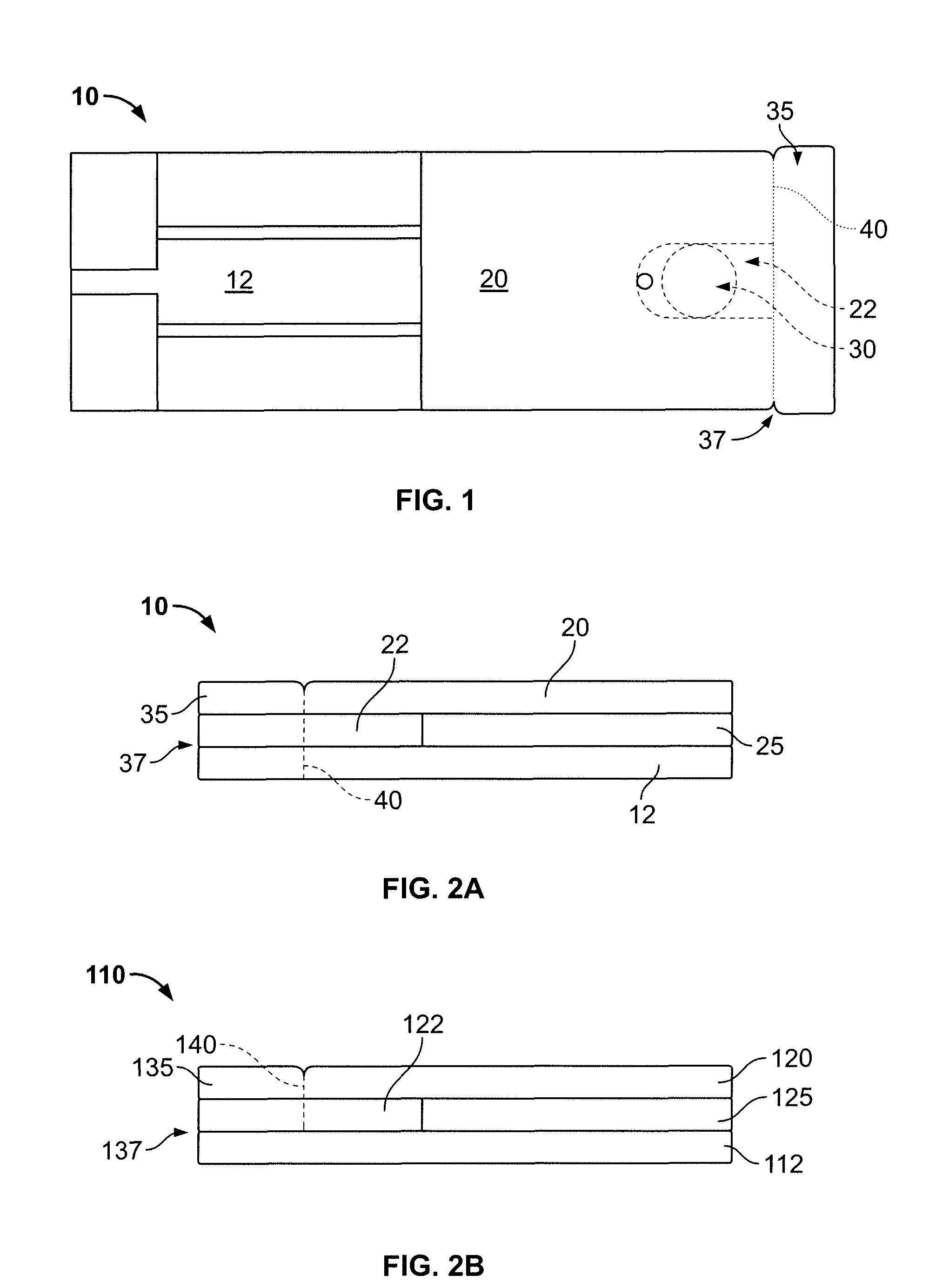
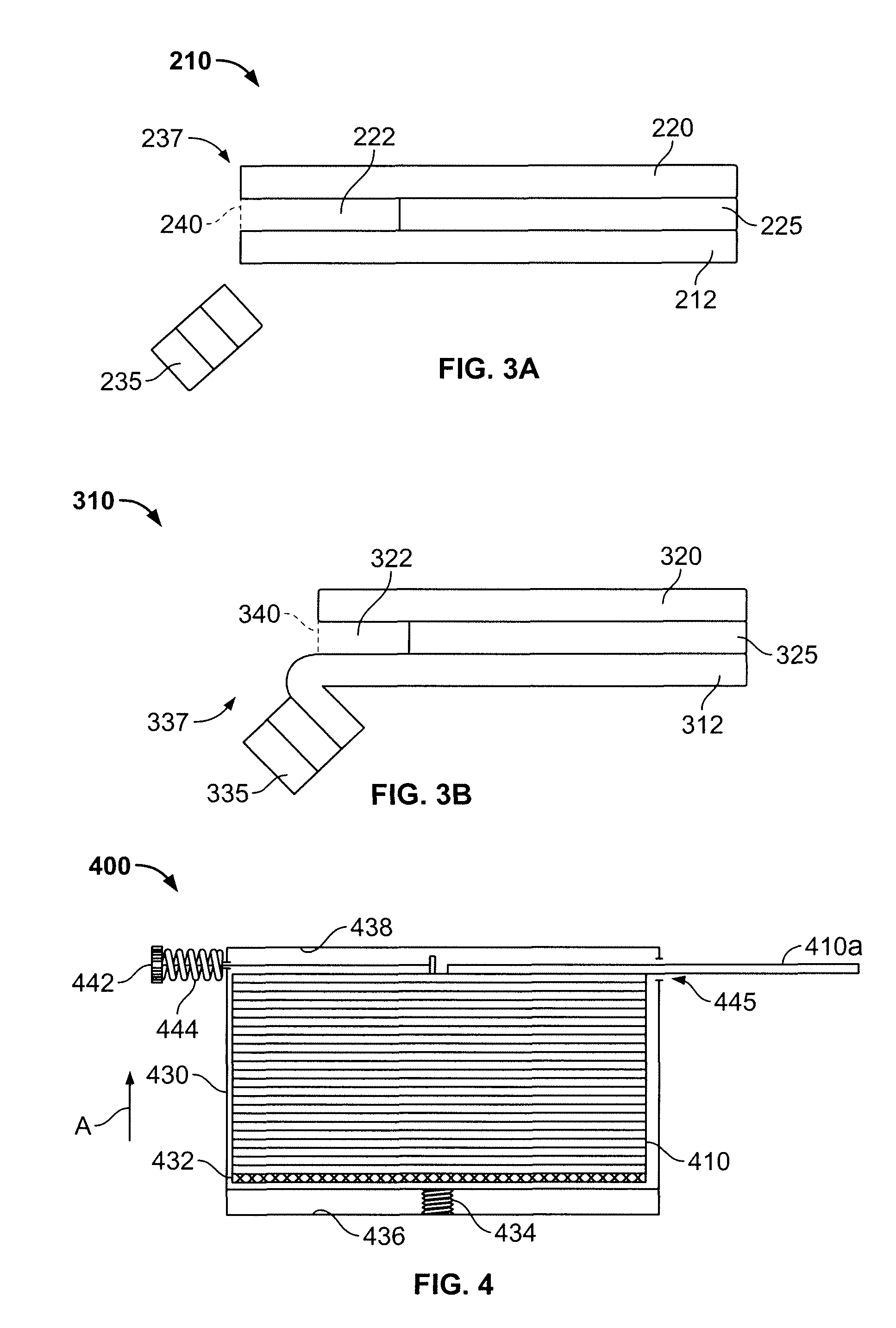
[0039]A test sensor comprising:

[0040]a base and a lid, the base and the lid assisting in forming a channel to receive a fluid sample, the channel including a reagent;

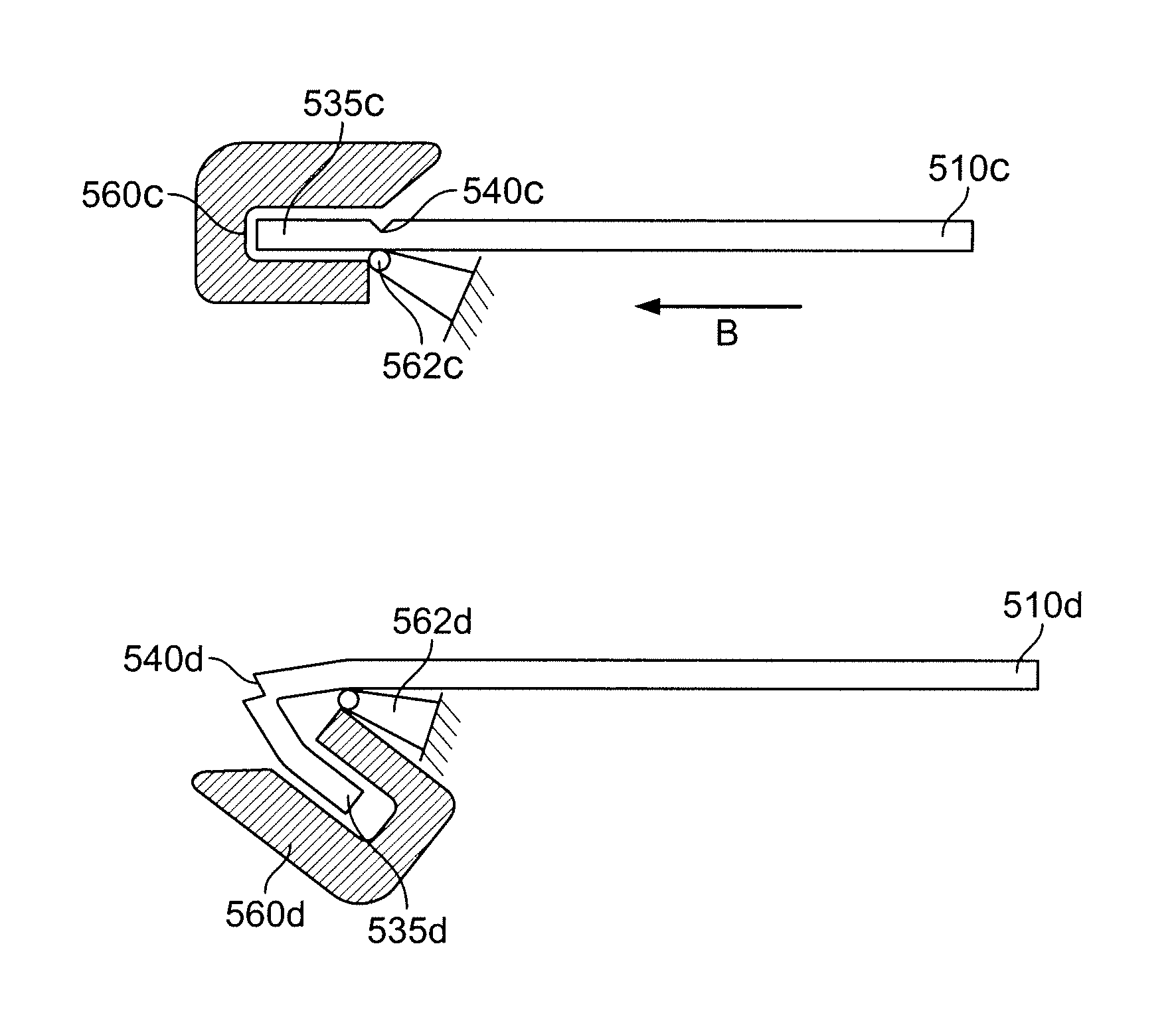
[0041]a tip portion extending from at least one of the base and lid, the tip portion preventing or inhibiting moisture or contaminants from entering the channel; and

[0042]a detachable area located adjacent the tip portion, the detachable area being formed so as to assist movement of the tip portion or removal of the tip portion from the remainder of the test sensor,

[0043]wherein the movement or removal of the tip portion exposes the channel for receiving the fluid sample.

embodiment b

[0044]The test sensor of alternative embodiment A wherein the detachable area extends through at least the lid of the test sensor.

embodiment c

[0045]The test sensor of alternative embodiment A wherein the detachable area extends through at least the lid and the base of the test sensor.


PUM

PropertyMeasurementUnit
areaaaaaaaaaaa
detachable areaaaaaaaaaaa
breakingaaaaaaaaaa

Abstract

A test sensor includes a base, a lid and a channel for receiving a fluid sample. The channel includes a reagent. The test sensor also includes a tip portion extending from at least one of the base and lid. The tip portion prevents or inhibits moisture or contaminants from entering the channel and affecting the reagent. The test sensor further includes a detachable area located adjacent the tip portion. The detachable area is formed so as to assist movement of the tip portion or removal of the tip portion from the remainder of the test sensor. The movement or removal of the tip portion exposes the channel for receiving the fluid sample.

Description

CROSS-REFERENCE TO RELATED APPLICATIONS[0001]This application is a U.S. national stage of International Application No. PCT / US2008 / 085807, filed Dec. 8, 2008, which claims the benefit of U.S. Provisional Application No. 61 / 007,179, filed Dec. 10, 2007, both of which are hereby incorporated by reference herein in their entireties.FIELD OF THE INVENTION[0002]The present invention generally relates to a test sensor for the measurement of analytes. More specifically, the present invention generally relates to a test sensor having a tip portion that is removable to expose an area for receiving a fluid sample.BACKGROUND OF THE INVENTION[0003]The quantitative determination of analytes in body fluids is of great importance in the diagnoses and maintenance of certain physiological abnormalities. For example, glucose, lactate, cholesterol and bilirubin should be monitored in certain individuals. In particular, it is important that individuals who are diabetics frequently check the glucose lev...

Claims


Application Information

Patent Timeline
Patent Type & Authority Patents(United States)
IPC IPC(8): G01N21/75
CPCB01L3/502715B01L3/523B01L3/502738B01L2200/027B01L2200/141B01L2300/041B01L2300/043B01L2300/0825B01L2300/0887
Inventor YAO, SIMIN
Owner ASCENSIA DIABETES CARE HLDG AG
Why Eureka
Try Eureka