Surgical fastener for applying a large staple through a small delivery port

a surgical and staple technology, applied in the field of surgical tissue fastening, can solve the problems of affecting the quality of life of individuals and consuming a lot of food. obesity and its co-morbidities are estimated to cost an excess of $100 billion dollars annually in direct and indirect health care costs

Active Publication Date: 2013-06-04
ETHICON ENDO SURGERY INC
View PDF100 Cites 228 Cited by
  • Summary
  • Abstract
  • Description
  • Claims
  • Application Information

AI Technical Summary

Problems solved by technology

Obesity affects an individual's quality of life and contributes significantly to morbidity and mortality.
Obesity and its co-morbidities are estimated to cost an excess of $100 billion dollars annually in direct and indirect health care costs.
These complications can affect all systems of the body, and dispel the misconception that obesity is merely a cosmetic problem.
Studies have shown that conservative treatment with diet and exercise alone may be ineffective for reducing excess body weight in many patients.
In another example, the procedure will limit the stomach's ability to expand, effectively reducing its capacity or fill volume.
This individual placement of the T-Tag anchors and manual suture tensioning is time intensive; increasing the duration, complexity and cost of the GVR procedure.
However, these devices suffer from a number of deficiencies which make them impractical for use in the GVR procedure.
However, the use of a soft ductile material decreases the strength and holding power of the formed staple, thus making the staple unsuitable for the pressures associated with involuting the gastric cavity wall without an impractical number of staples.
However, the triangular shape of these staples prevents the staples from being stacked and fed longitudinally through the stapler shaft.

Method used


Image

  • Surgical fastener for applying a large staple through a small delivery port
  • Surgical fastener for applying a large staple through a small delivery port
  • Surgical fastener for applying a large staple through a small delivery port

Examples


Embodiment Construction

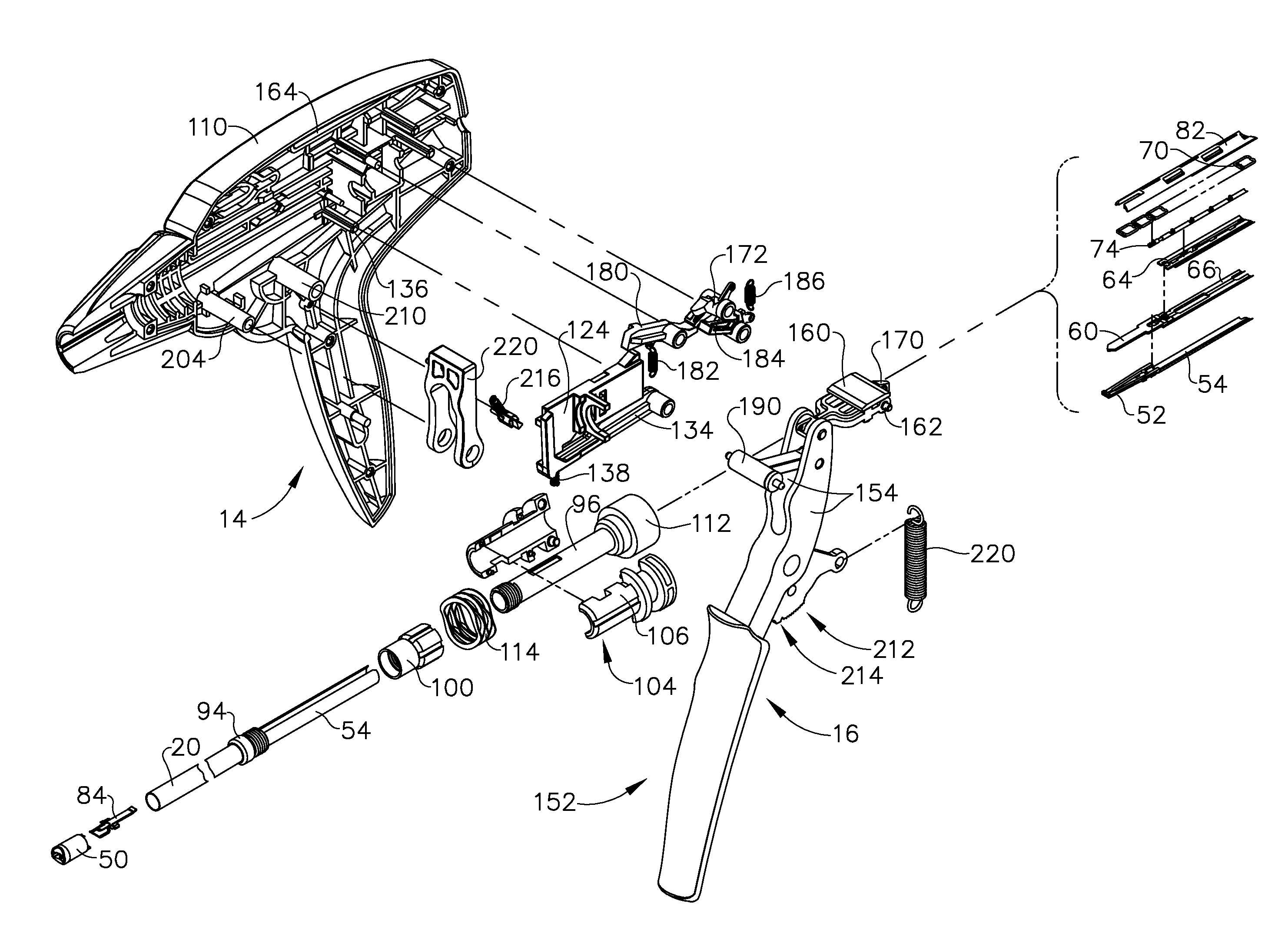
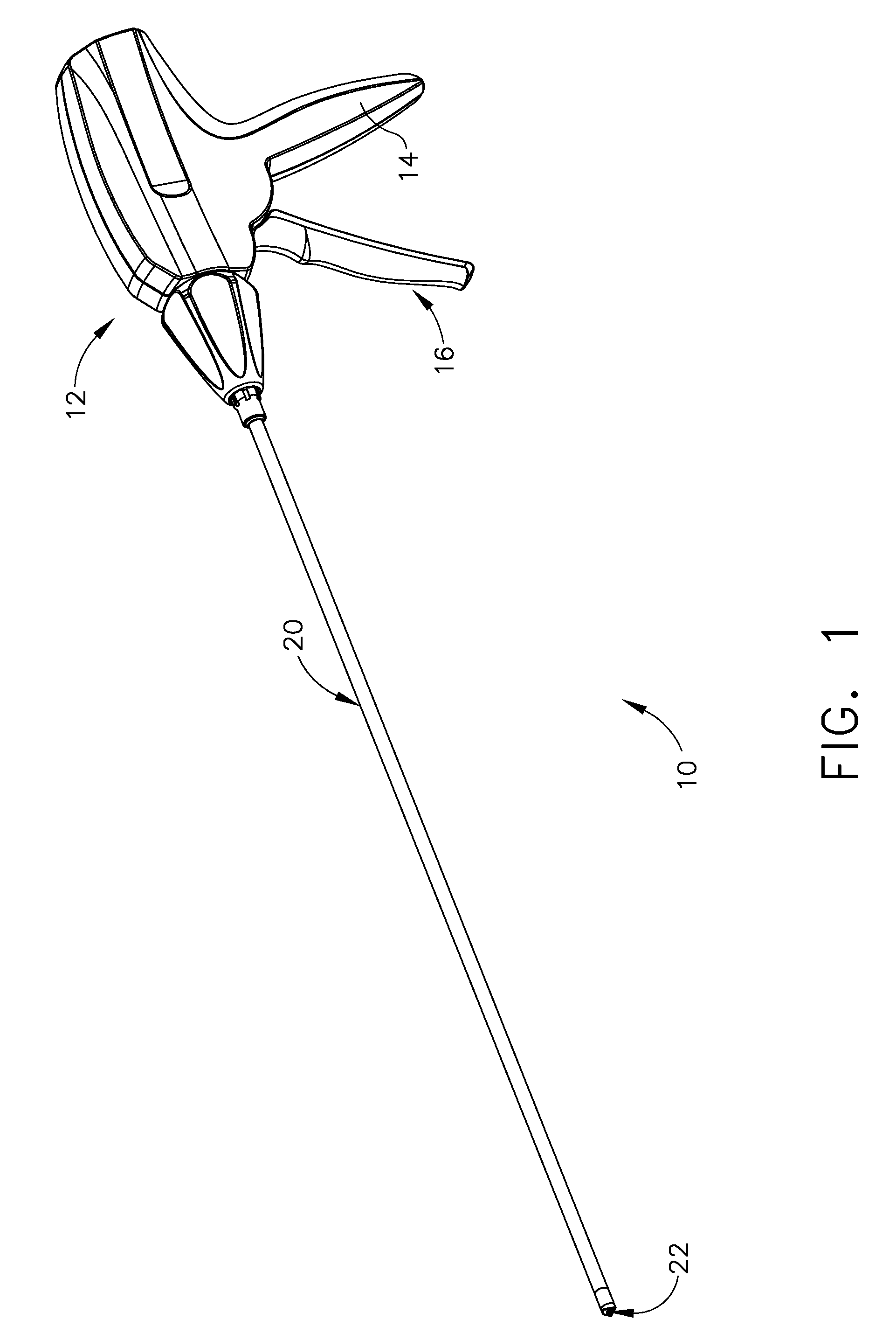
[0050]Referring now to the drawing figures, in which like numerals indicate like elements throughout the views, FIG. 1 illustrates an exemplary low profile fastener applying device or stapler for use in GVR and other small incision site surgical procedures in the peritoneal cavity including, but not limited to, reinforcement of staple lines (e.g., “over-sewing” of a vertical sleeve gastrectomy), closing of surgical defects (e.g., gastronomy closure), and fixation of temporary (e.g., liver retraction) or permanent (e.g., hernia mesh, gastric band securement) medical devices. As shown in FIG. 1, the stapler 10 includes a handle 12 having a pistol grip 14 shaped for grasping by a surgeon. A trigger or actuator 16 is pivotably attached to handle 12 to be drawn towards the pistol grip 14 in a trigger plane during staple deployment. An elongated staple housing 20 having a longitudinal axis extends distally from handle 12. Housing 20 has sufficient length (on the order of 18″) to enable us...


PUM

PropertyMeasurementUnit
diameteraaaaaaaaaa
diameteraaaaaaaaaa
diameteraaaaaaaaaa

Abstract

A surgical fastener applying device having a handle with a trigger pivotably attached thereto and movable within a trigger plane. The trigger has a bottom portion extending from the handle and a top portion disposed within a housing of the handle. The device has a staple housing with a proximal end attached to the handle, a distal end extending therefrom and a longitudinal axis therebetween. The housing has a firing bar disposed within, and the trigger is coupled to the firing bar. The device has a link member with a first end pivotably attached to the top portion of trigger, the link member has a second end comprising a slidable pin. The pin engages a three dimensional cam path disposed within the housing. The link member follows distal and proximal movement of the top portion of the trigger, and the pin slides perpendicular to the trigger plane to follow the three dimensional cam path.

Description

REFERENCE TO RELATED APPLICATIONS[0001]This application is a continuation-in-part of U.S. application Ser. No. 13 / 015,977 filed on Jan. 28, 2011; and is a continuation-in-part of U.S. patent application Ser. No. 13 / 015,966 filed on Jan. 28, 2011; and is a continuation-in-part of U.S. patent application Ser. No. 12 / 690,311 filed on Jan. 20, 2010; and is a continuation-in-part of U.S. patent application Ser. No. 12 / 690,285 filed on Jan. 20, 2010; and is a continuation-in-part of U.S. patent application Ser. No. 12 / 608,860 filed on Oct. 29, 2009; and is a continuation-in-part of U.S. patent application Ser. No. 12 / 609,336 filed on Oct. 30, 2009; and is a continuation-in-part of U.S. patent application Ser. No. 12 / 359,351 filed on Jan. 26, 2009; and is a continuation-in-part of U.S. patent application Ser. No. 12 / 359,354 filed on Jan. 26, 2009; and is a continuation-in-part of U.S. patent application Ser. No. 12 / 359,357 filed on Jan. 26, 2009.FIELD OF THE INVENTION[0002]The present inve...

Claims


Application Information

Patent Timeline
Patent Type & Authority Patents(United States)
IPC IPC(8): A61B17/68
CPCA61B17/0644A61B17/0682A61B17/0684
Inventor HOLCOMB, MATTHEW D.HARRIS, JASON L.STOKES, MICHAEL J.CERIER, JEFFREY C.O'KEEFE, JONATHAN B.BOUDREAU, KEITH D.ZEINER, MARK S.
Owner ETHICON ENDO SURGERY INC
Why Eureka
Try Eureka