Beam clamp

a beam clamp and beam technology, applied in the field of beam clamping, can solve the problems of affecting the performance of the beam clamp, the tendency of the beam clamp to twist, and the inability of other methods to achieve the effect of preventing the beam from loosening and loosing

Active Publication Date: 2013-07-09
MYERS MELVIN L
View PDF27 Cites 31 Cited by
  • Summary
  • Abstract
  • Description
  • Claims
  • Application Information

AI Technical Summary

Benefits of technology

[0023]Larger objects are clamped using additional holes. This allows additional threaded fasteners, for pulling the two bodies of the clamp together. Flanges or ribs are added, to the bodies, to strengthen the clamps.

Problems solved by technology

This type of clamp has a greater tendency to twist, pivoting about the bolt that carries the load, possibly leading to the loosening of the bolt.
Other methods are not capable of this.

Method used


Image

  • Beam clamp
  • Beam clamp
  • Beam clamp

Examples


Embodiment Construction

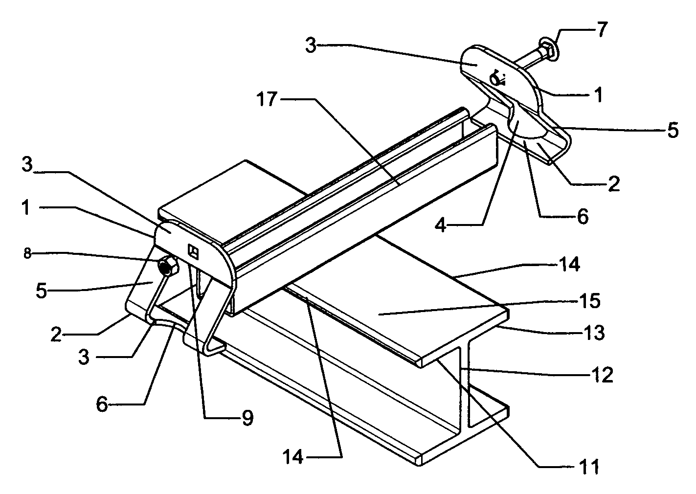
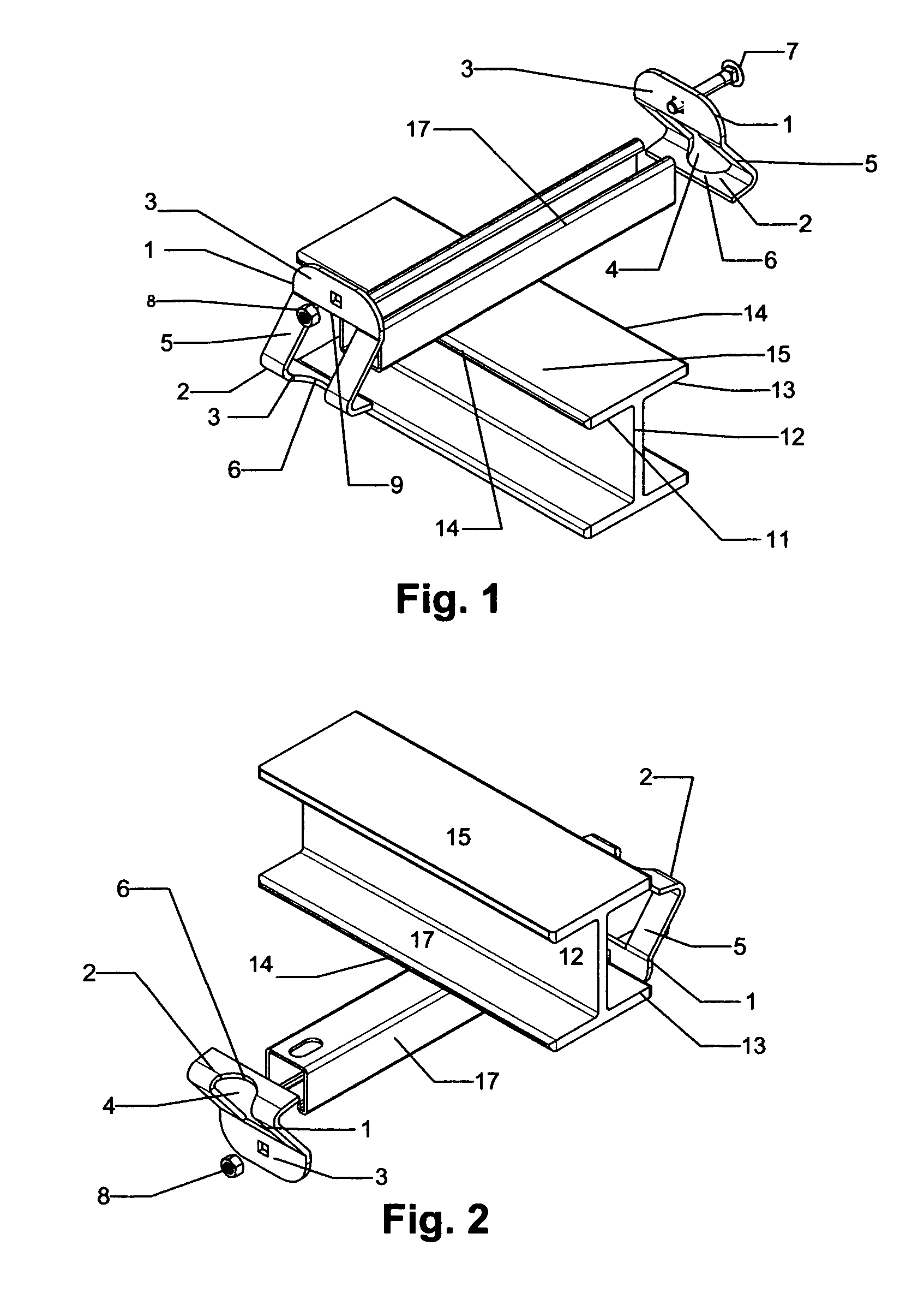
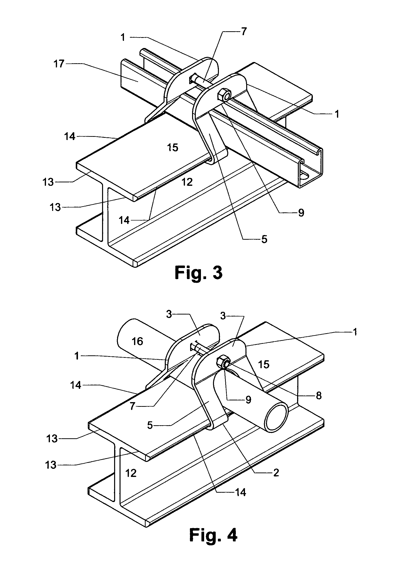
[0101]Beam Clamp assembly comprised of two substantially the same opposing bodies 1, with one or more member passage 4, for a corresponding number of elongated objects to pass. The elongated objects, including a round member 16, and a rectangular member 17, being attached against the structure bearing surface 15, and perpendicular to or at an angle of between 40 degrees and 90 degrees to the structure edge 14, of structure member 12, to which the assembly is attached. A method of fastening and pulling towards each other the pulling ends 3, of the clamp body 1, such as a bolt 7, and a nut 8, is included.

[0102]The clamp bodies 1, inside surfaces that face each other are substantially shaped like an “?”, “S”, “2” or “Z” with the hook end 6, forming an acute angle and the bolt end 3, forming an obtuse angle with an optional flange 28 added to the pulling end 3, at preferably a right angle in either direction. Additional features such as flanges 28, ribs 27 can be added to strengthen and...


PUM


Abstract

A beam clamp providing for a positive attachment to I-beams, H-beams, T-bars, pairs of conventional angles, bulb angles, channels, plates and other similar structural shapes wherein the beam clamp includes a pair of clamping hooks incorporated into opposing clamp bodies that capture an attached elongated rectangular, round or other shape. The shapes are secured against the structure using one or more bolt with nut assemblies to pull the halves together towards each other and the attached member and towards the structure.

Description

CROSS-REFERENCE TO RELATED APPLICATIONS[0001]Provisional patent application 61 / 217,142 with a filing date of May 27, 2009 and provisional patent applications 61 / 217,673 filed on Jun. 3, 2009 and 61 / 217,141 filed on May 27, 2009 and being submitted as a non provisional patent application along with this one.FEDERALLY SPONSORED RESEARCH[0002]Not ApplicableSEQUENCE LISTING OR PROGRAM[0003]Not applicableREFERENCES CITED[0004]U.S. Pat. No. 6,334,285B1 Jan. 1, 2002 Kirschner 52 / 702BACKGROUND[0005]1. Field[0006]This application relates to the attaching of structural and accessory members to each other. Specifically for attaching, a member to beams or other structural configurations that have 2 fixed opposing edges that allow opposing clamp halves to hook around and the attaching member be held against one or more surfaces that is oriented in a planar surface generally between the opposing edges as a I-Beam embodies.[0007]2. Prior Art[0008]Clamps are often used as hangers for supporting and...

Claims


Application Information

Patent Timeline
Patent Type & Authority Patents(United States)
IPC IPC(8): F16L3/24F16B1/00
CPCF16L3/1211F16B2/12F16B7/0493Y10T24/14Y10T403/7062Y10T403/7105Y10T403/7171Y10T403/7067Y10T403/64Y10T403/7194Y10T24/44Y10T24/44017F16B2200/50
Inventor MYERS, PHILIP ALLEN
Owner MYERS MELVIN L
Why Eureka
Try Eureka