Burner fuel staging

a technology of burner fuel and burner body, which is applied in the field of burner fuel staging, can solve the problems of significant increase in the rate of nitrous oxide formation and damage to the environment, and achieve the effect of low formation ra

Inactive Publication Date: 2013-07-16
SIEMENS AG
View PDF24 Cites 3 Cited by
  • Summary
  • Abstract
  • Description
  • Claims
  • Application Information

AI Technical Summary

Benefits of technology

[0011]An object of the invention is to provide an improved fuel-air premixing arrangement for operating a burner over various machine loads with low rate of formation of nitrous oxides and a method of operating such a fuel-air premixing arrangement.

Problems solved by technology

However, burning the fuel leads to a number of pollutants in the exhaust gas which can cause damage to the environment.
However, for power output requirements different from the design point, the rate of formation of nitrous oxides may increase significantly.

Method used


Image

  • Burner fuel staging
  • Burner fuel staging
  • Burner fuel staging

Examples


Embodiment Construction

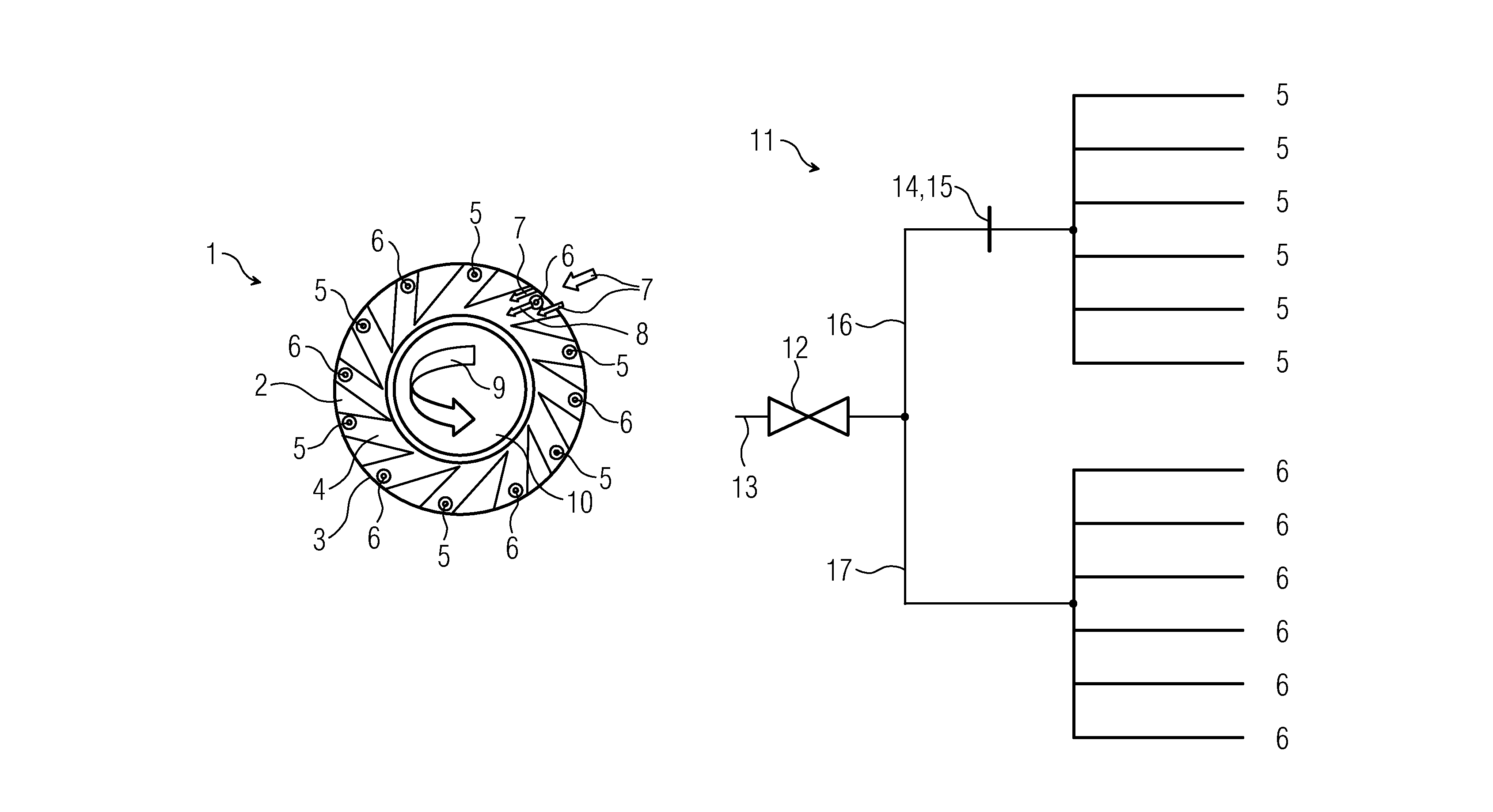
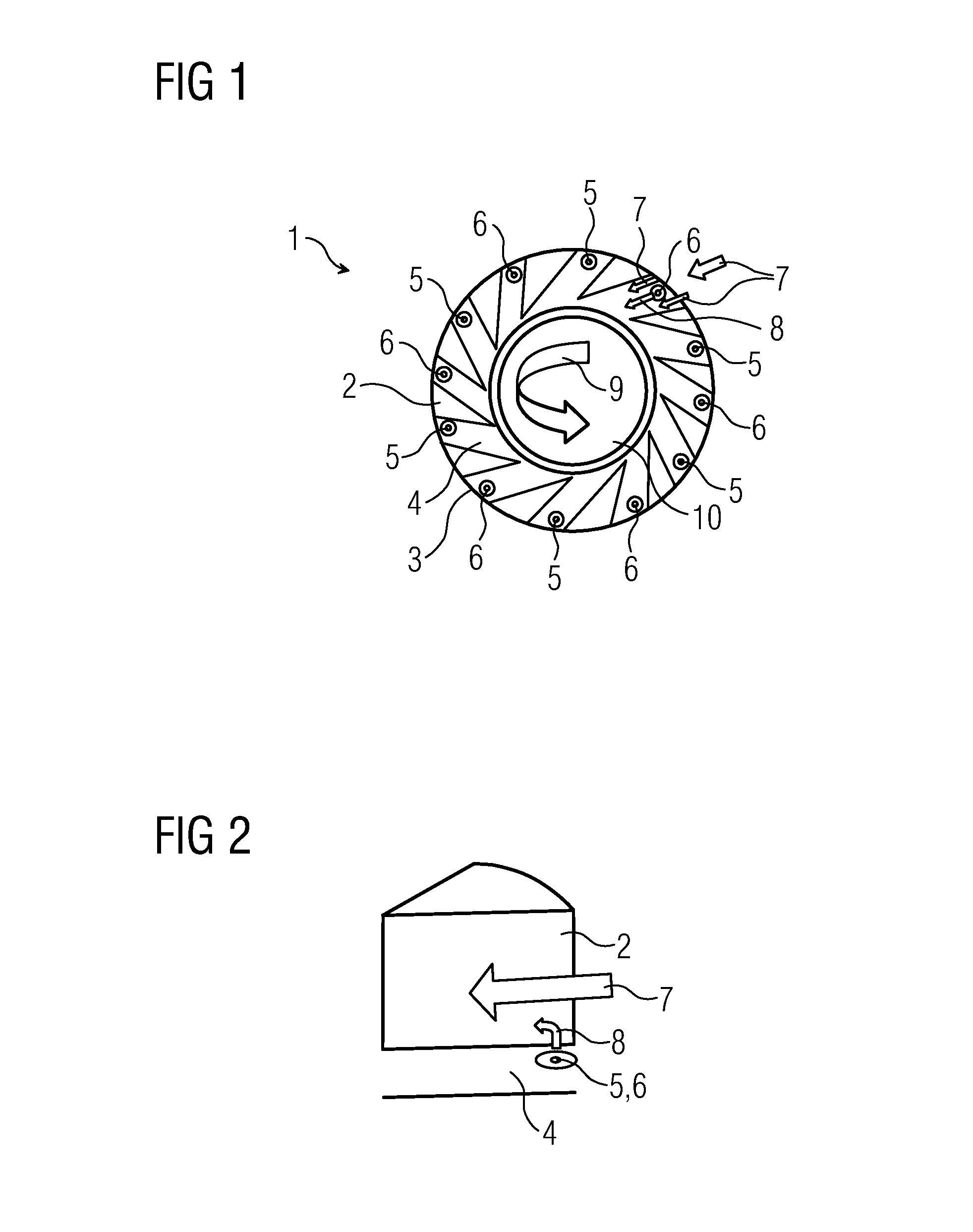
[0035]FIG. 1 illustrates a typical swirler 1 used as premix fuel injection system in a gas turbine engine. The swirler 1 comprises twelve swirler vanes 2 arranged on a swirler vane support 3. The swirler vanes 2 can be fixed to a burner head with their sides showing away from the swirler vane support 3. Neighbouring swirler vanes 2, burner head and swirler vane support 3 form swirler passages 4. Usually, fuel injection openings 5,6 are arranged in these swirler passages 4.

[0036]During operation of the burner, compressor air 7 flows into the swirler passages 4. Within the swirler passages 4 fuel 8 is injected through the fuel injection openings 5,6 into the streaming compressor air 7. The fuel / air mixture 9 then leaves the swirler passage 4 and streams through a central opening 10 of the swirler vane support 3 into a pre-chamber (not shown) and to the combustion zone, where it is burned.

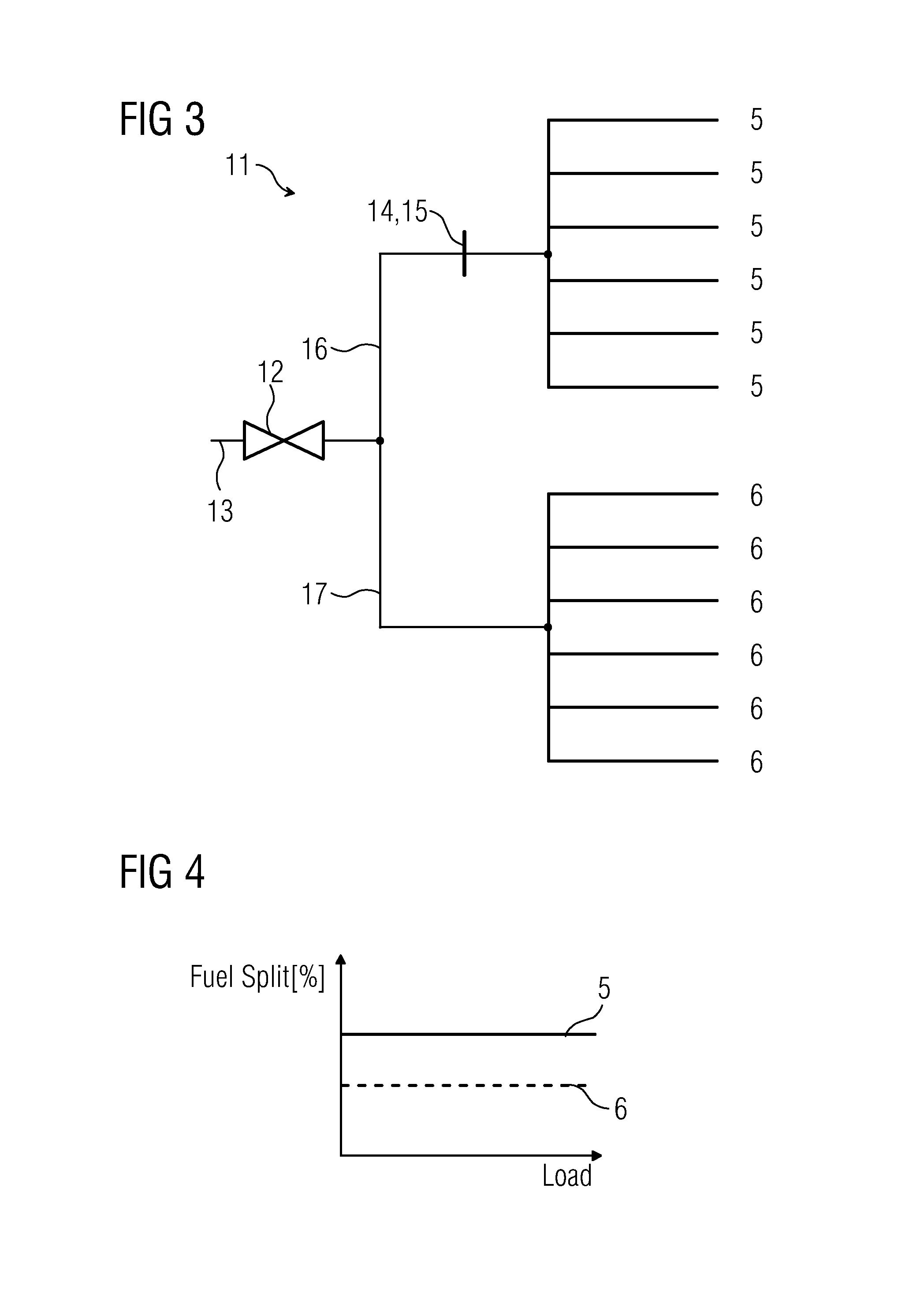
[0037]In FIG. 1, the fuel injection openings 5 and 6, although identical from a design-engineering...


PUM


Abstract

A fuel-air premixing arrangement includes a plurality of fuel injection openings. The fuel injection openings are grouped into at least two groups and arranged on one circle in alternating order. Each group has a common rail for supplying fuel to the respective group. A valve element is arranged in at least one common rail.

Description

CROSS REFERENCE TO RELATED APPLICATIONS[0001]This application is the US National Stage of International Application No. PCT / EP2008 / 052875, filed Mar. 11, 2008 and claims the benefit thereof. The International Application claims the benefits of European application No. 07005408.5 filed Mar. 15, 2007 both of the applications are incorporated by reference herein in their entirety.FIELD OF THE INVENTION[0002]The invention relates to a burner and a method of operating a burner with staged fuel supply.BACKGROUND OF THE INVENTION[0003]In a burner of a gas turbine fuel is burnt to produce hot pressurized mainstream gases which are led to a turbine stage where they, while expanding and cooling, transfer momentum to turbine blades thereby imposing a rotational movement on a turbine rotor. Mechanical power of the turbine rotor can then be used to drive a generator for producing electrical power or to drive a machine. However, burning the fuel leads to a number of pollutants in the exhaust gas ...

Claims


Application Information

Patent Timeline
Patent Type & Authority Patents(United States)
IPC IPC(8): F02C1/00
CPCF23R3/346
Inventor LAM, KAM-KEI
Owner SIEMENS AG
Why Eureka
Try Eureka