Valve sealing arrangements and methods

a sealing arrangement and valve technology, applied in the direction of valve details, valve arrangements, plug valves, etc., can solve the problems of unbalanced passage pressure load bias, limited sealing force, and reduced net effective area

Inactive Publication Date: 2013-07-23
SWAGELOK CO
View PDF21 Cites 21 Cited by
  • Summary
  • Abstract
  • Description
  • Claims
  • Application Information

AI Technical Summary

Problems solved by technology

In one embodiment, the sealing forces may be limited by reducing the net effective area upon which the upstream fluid pressure may act.
The valve may be adapted such that when the fluid pressure in the fluid passage exceeds the fluid pressure in the valve cavity, an unbalanced passage pressure load (resulting from outward facing seat member surfaces exceeding inward facing seat member surfaces within the fluid passage) exerts a fluid driven or pressure assisted sealing force to bias the valve seat into sealing engagement with the valve element.
The valve may be further adapted such that when the fluid pressure in the valve cavity exceeds the fluid pressure in the fluid passage, an unbalanced cavity pressure load (resulting from outward facing seat member surfaces exceeding inward facing seat member surfaces within the valve cavity) exerts a fluid driven or pressure assisted sealing force to bias the valve seat into sealing engagement with the valve element.
When the pressure in the fluid passage exceeds the pressure in the valve cavity, an unbalanced passage pressure load biases the seat member toward sealing engagement with the valve element.
When the pressure in the valve cavity exceeds the pressure in the fluid passage, an unbalanced cavity pressure load biases the seat member toward sealing engagement with the valve element.

Method used


Image

  • Valve sealing arrangements and methods
  • Valve sealing arrangements and methods
  • Valve sealing arrangements and methods

Examples


Embodiment Construction

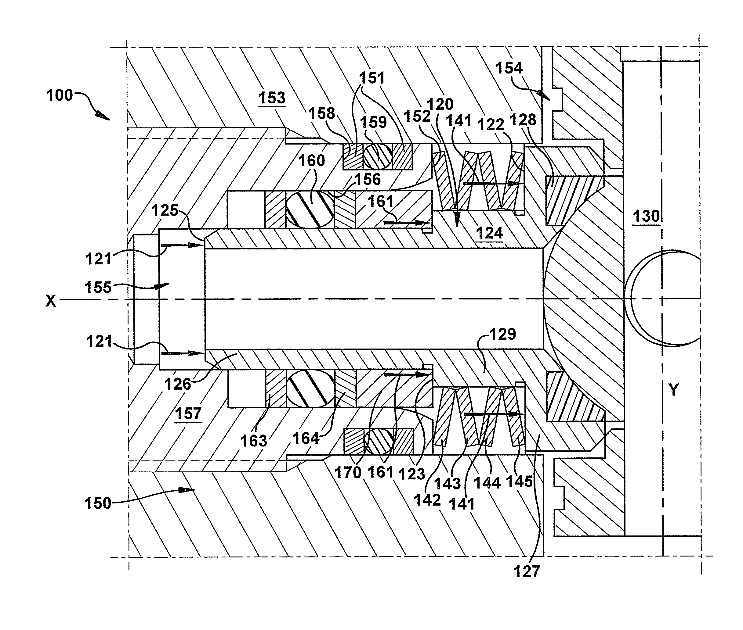
[0041]The present application relates to sealing arrangements that may be used with many types of valves, such as, for example, ball valves. While the sealing arrangements described herein are described as used with rotary ball valves (such as, for example, a quarter-turn shutoff ball valve), the inventive sealing arrangements described herein may be used with many different types of valves, including, for example, plug valves and gate valves, and with valves configured to perform many different functions, including, for example, switching and regulating valves. In one embodiment, a valve includes a movable valve element, operable to control the flow of fluid directed into the valve, and a valve seat member, configured to seal against the valve element to limit or prevent fluid leakage around or past the valve element.

[0042]According to an inventive aspect of the present application, a valve sealing arrangement may be configured to apply, to a valve seat member, an unbalanced passag...


PUM


Abstract

A valve includes a valve body, a valve element to selectively control flow through the valve, and a seal member and seat member together providing a fluid-tight seal between a valve cavity and a fluid passage in the valve body. A live-loaded biasing member is adapted to apply a live-loaded sealing force to the seat member to bias the seat member toward sealing engagement with the valve element. When the pressure in the fluid passage exceeds the pressure in the valve cavity, an unbalanced passage pressure load biases the seat member toward sealing engagement with the valve element. When the pressure in the valve cavity exceeds the pressure in the fluid passage, an unbalanced cavity pressure load biases the seat member toward sealing engagement with the valve element. The live-loaded sealing force is in parallel with each of the unbalanced passage pressure load and the unbalanced cavity pressure load.

Description

CROSS-REFERENCE TO RELATED APPLICATION[0001]This application claims the benefit of pending U.S. provisional application Ser. No. 61 / 104,808 filed on Oct. 13, 2008, entitled VALVE SEALING ARRANGEMENTS AND METHODS, the entire disclosure of which is fully incorporated herein by reference.BACKGROUND OF THE DISCLOSURE[0002]Valves are often used to control fluid flow through a fluid system, for example, by shutting off, regulating, or redirecting flow applied to an inlet fluid passage of the valve. In many valves, a valve element is selectively movable to block, meter, divert, or otherwise control fluid flow, for example, to another passage of the valve, such as an outlet passage. Such a valve element may be placed in sealing engagement with one or more valve seat members, to limit or prevent leakage of system fluid past the valve element. Valve elements may be movable in a variety of different ways with respect to the seat member, including, for example, axial movement of the valve eleme...

Claims


Application Information

Patent Timeline
Patent Type & Authority Patents(United States)
IPC IPC(8): F16K25/00
CPCF16K5/188F16K5/205
Inventor KEEPER, BRANDEN W.GLIME, WILLIAM H.
Owner SWAGELOK CO
Why Eureka
Try Eureka