Multi-cycle dump valve

a dump valve and multi-cycle technology, applied in the direction of fluid removal, wellbore/well accessories, sealing/packing, etc., can solve the problems of time-consuming and laborious cleaning operation, damage to the zone above the treatment zone, and inoperable wellbores

a dump valve and multi-cycle technology, applied in the direction of fluid removal, wellbore/well accessories, sealing/packing, etc., can solve the problems of time-consuming and laborious cleaning operation, damage to the zone above the treatment zone, and inoperable wellbores

US20040084190A1Inactive Publication Date: 2004-05-06SCHLUMBERGER TECH CORP

Image

  • Multi-cycle dump valve
  • Multi-cycle dump valve
  • Multi-cycle dump valve

Examples


Embodiment Construction

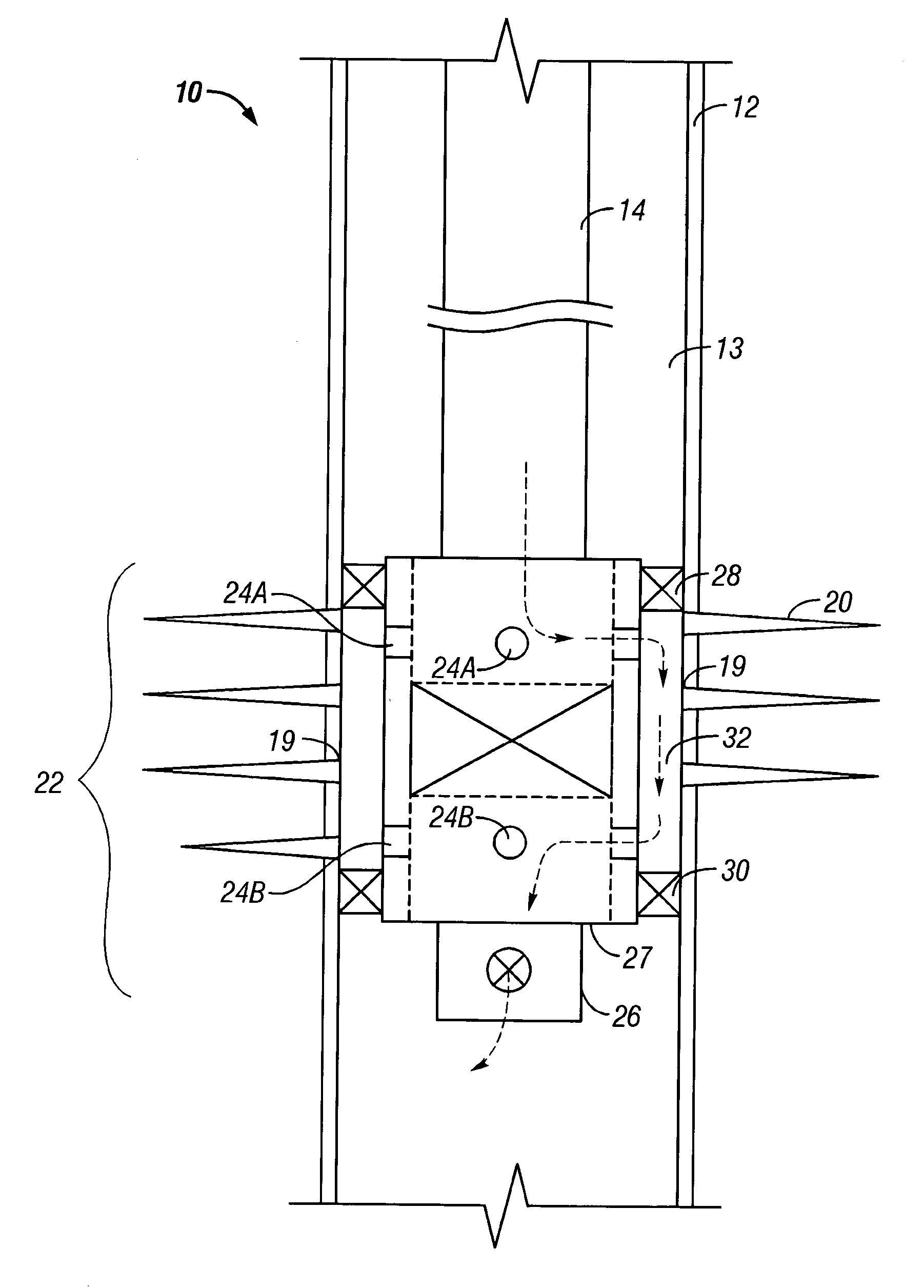
[0037] In the following description, numerous details are set forth to provide an understanding of the present invention. However, it will be understood by those skilled in the art that the present invention may be practiced without these details and that numerous variations or modifications from the described embodiments may be possible. For example, although reference is made to a fracturing string in the described embodiments, other types of tubing conveyed downhole well tools may be employed in further embodiments.

[0038] As used here, the terms "up" and "down"; "upward" and downward"; "upstream" and "downstream"; and other like terms indicating relative positions above or below a given point or element are used in this description to more clearly described some embodiments of the invention. However, when applied to equipment and methods for use in wells that are deviated or horizontal, such terms may refer to a left to right, right to left, or other relationship as appropriate. ...


PUM


Abstract

A flow responsive dump valve mechanism for a straddle packer tool and has a valve controlled flow passage from which underflushed fluid, typically well treatment slurry, in a conveyance and fluid supplying tubing string can be dumped into a well casing. The dump valve mechanism incorporates a ratcheting power piston, an indexing mechanism and high and low load energy storage systems to accomplish open, closed and intermediate dump valve positions. The intermediate position increases the functionality of the tool by preventing accidental closure either due to the free fall of fluid through the coiled tubing or during flushing of the tool and permits the flow rate to be increased for thorough cleaning of the straddle tool and coiled tubing. For energy storage, a light compression spring provides power to cycle the indexing mechanism. Heavier load disc springs (Bellville Washers) are used to provide power for the ratcheting power piston to open the valve.

Description

[0001] 1. Related Invention[0002] The present invention relates to the subject matter of commonly assigned United States Patent Publication No. US 202 / 0062963 A1, of David M. Eslinger et. al, published on May 30, 2002, and issued as U.S. Pat. No. 6,533,037 on Mar. 18, 2003, which Publication and Patent are incorporated herein by reference for all purposes. Applicants hereby claim priority in United States Provisional Application No. 60 / 422,285, filed on Oct. 30, 2002 by Stephen D. Hill, Robert Bucher, L. Michael McKee, Mark Oettli and Michael Gay and entitled "Dump Valve" and incorporate said Provisional Application by reference herein for all purposes.[0003] 2. Field of the Invention[0004] The present invention relates generally to straddle tools for use in wellbores for stimulation or fracturing of packer isolated annulus intervals and more particularly to straddle tools having valves that are actuated to cause dumping into the well below the straddle tool fluids from a conveyance...

Claims


Application Information

Patent Timeline
06 May 2004
Publication
US20040084190A1
IPC
E21B23/00; E21B33/124; E21B34/06; E21B34/08; E21B34/14
CPC
E21B23/006; E21B33/124; E21B34/14; E21B34/08; E21B34/063; E21B43/26
Inventors
HILL, STEPHEN D.; BUCHER, ROBERT