Optical network restoration

a network restoration and optical network technology, applied in the field of optical network restoration, can solve the problems of significant bandwidth loss, inability of hybrid equipment to take full advantage of statistical multiplexing capabilities provided by packet technology, and inability to implement such a vt/sts path protection method

Inactive Publication Date: 2005-10-04
WHITE OAK GLOBAL ADVISORS
View PDF17 Cites 124 Cited by
  • Summary
  • Abstract
  • Description
  • Claims
  • Application Information

AI Technical Summary

Benefits of technology

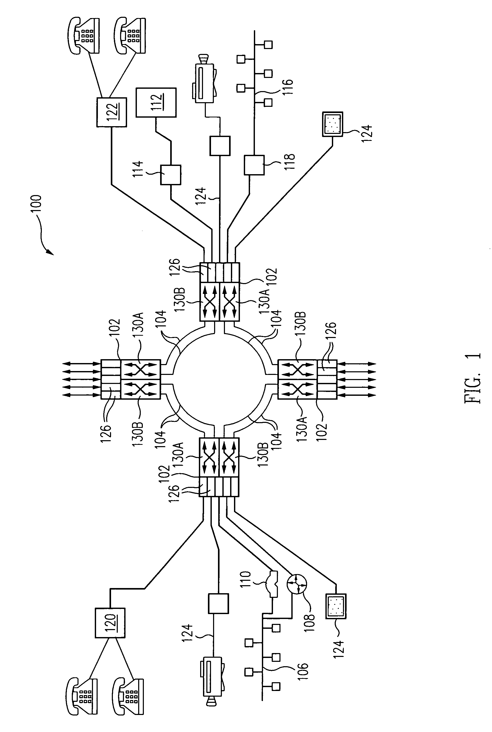
[0023]When a fault in the traffic in an active PPG is detected, e.g., a cut in the fiber on which the PPG is carried, the method includes the generation of a protection switching signal (“PSS”) by the nodes detecting the fault, and the transmission of that signal in the respective MCFs of each PPG affected by the fault, i.e., each PPG carried on the cut fiber, to the relevant “protection switching entities” (“PSEs”), viz., one or both of the I / E nodes themselves, which then responsively switch either the receipt of the affected traffic, in a system operating in “bridged” mode, or both the transmission and the receipt of the affected traffic, in a system operating in an “un-bridged” mode, from the affected “active” PPG to the associated “protect” PPG to thereby restore path and signal continuity within the system.

Problems solved by technology

However, “pure packet” (e.g. ATM, MPLS, or IP) based equipments implementing such a VT / STS path protection method cannot take advantage of the statistical multiplexing ability afforded by packet technology without the use of some form of external grooming equipment, e.g., ATM switches, IP routers, IP switches, and MPLS switches.
However, existing VP path protection standards do not support so-called “self-healing” rings, nor do they support TDM traffic unless it is first ATM-ized, with the resultant significant loss in bandwidth problem described above.
However, this method does not permit a hybrid equipment to take full advantage of the statistical multiplexing capabilities provided by packet technologies.

Method used


Image

  • Optical network restoration
  • Optical network restoration
  • Optical network restoration

Examples


Embodiment Construction

[0046]ATM was chosen by the ITU as the BISDN “universal” network and transport protocol for a broad range of user information, including voice, data, and video, over a user-to-network interface (“UNI”). ATM uses a high-speed “fast packet” or “cell relay” method of switching and transport to transmit information in the form of short, fixed-length “cells” across both private and public networks by reference to “virtual path” and “virtual channel” (“VPI” / “VCI”) addresses contained within the cells (i.e., “asynchronously”), rather than by reference to a fixed timing event (i.e., “synchronously”). The chief benefits of ATM are its ability, through the technique of statistical multiplexing, to provide increased effective bandwidth, i.e., “bandwidth on demand,” for “bursty,” asychronous types of data traffic, while at the same time delivering the traffic at specific Quality of Service (“QoS”) levels.

[0047]The term “SDH” refers to the international “Synchronous Digital Hierarchy” standard d...


PUM


Abstract

A method for protecting the flows of traffic against, and for restoring them from, a failure in a multifunctional, hybrid broadband access-and-transport network system includes the provisioning of at least two Virtual Flows (“VFs”) of traffic between each pair of ingress and egress (“I / E”) nodes in the system. The at least two VFs are provisioned such that each takes a different physical path from the other. The VFs taking the same physical path are then respectively grouped into two “Path Protection Groups” (“PPGs”). Each of the PPGs has a dedicated “Management Control Flow” (“MCF”) provisioned within it that is carried in the at least one VF contained therein. The detection of a fault in the traffic in an “active” PPG results in the generation of a protection switching signal (“PSS”) being generated and sent by the nodes detecting the fault along the MCF of the affected PPG to the relevant “protection switching entities” (“PSEs”), i.e., the affected I / E nodes, which responsively effect a protection switch of either the reception, or both the transmission and the reception, of the affected traffic from the affected “active” PPG to the associated “protect” PPG to thereby restore path and traffic continuity within the system. The method is independent of the transport layer and can thus be used to protect traffic in networks having transport systems other than SONET.

Description

RELATED APPLICATIONS[0001]This application is related to U.S. application Ser. No. 09 / 793,071, filed Feb. 26, 2001.BACKGROUND[0002]1. Technical Field[0003]This invention relates generally to telecommunications, and more particularly, to a method for restoring internal path and equipment failures in a hybrid broadband access-and-transport network system.[0004]2. Related Art[0005]Two closely interrelated segments of multi-service networking are “access” and “transport.”“Access” refers to the technology by which users connect to a wide area network (“WAN”), and through it, to service providers or other users connected to the WAN at locations remote from the user. “Transport” refers to the technologies that make up the fabric of the WAN itself, including those relating to the transmission of the users' information across the WAN.[0006]One model of a high-speed access-and-transport network system for which detailed standards have been developed by the International Telecommunication Unio...

Claims


Application Information

Patent Timeline
Patent Type & Authority Patents(United States)
IPC IPC(8): H04L12/26H04J14/02H04L12/24H04L12/56
CPCH04J14/0227H04J14/0283H04L41/0663H04L45/22H04L45/28H04L45/50H04J14/0238H04J14/0241
Inventor MANOHARAN, MADANGOPALAN, ARAVINDVADI, SRIKANTH R.
Owner WHITE OAK GLOBAL ADVISORS
Why Eureka
Try Eureka