Sensor assembly and medical device incorporating same
a technology applied in the field of sensors and medical devices, can solve the problems of relatively high sensitivity and/or accuracy of relativly small force sensors, and may be more susceptible to damag
- Summary
- Abstract
- Description
- Claims
- Application Information
AI Technical Summary
Benefits of technology
Problems solved by technology
Method used
Image
Examples
first embodiment
[0035
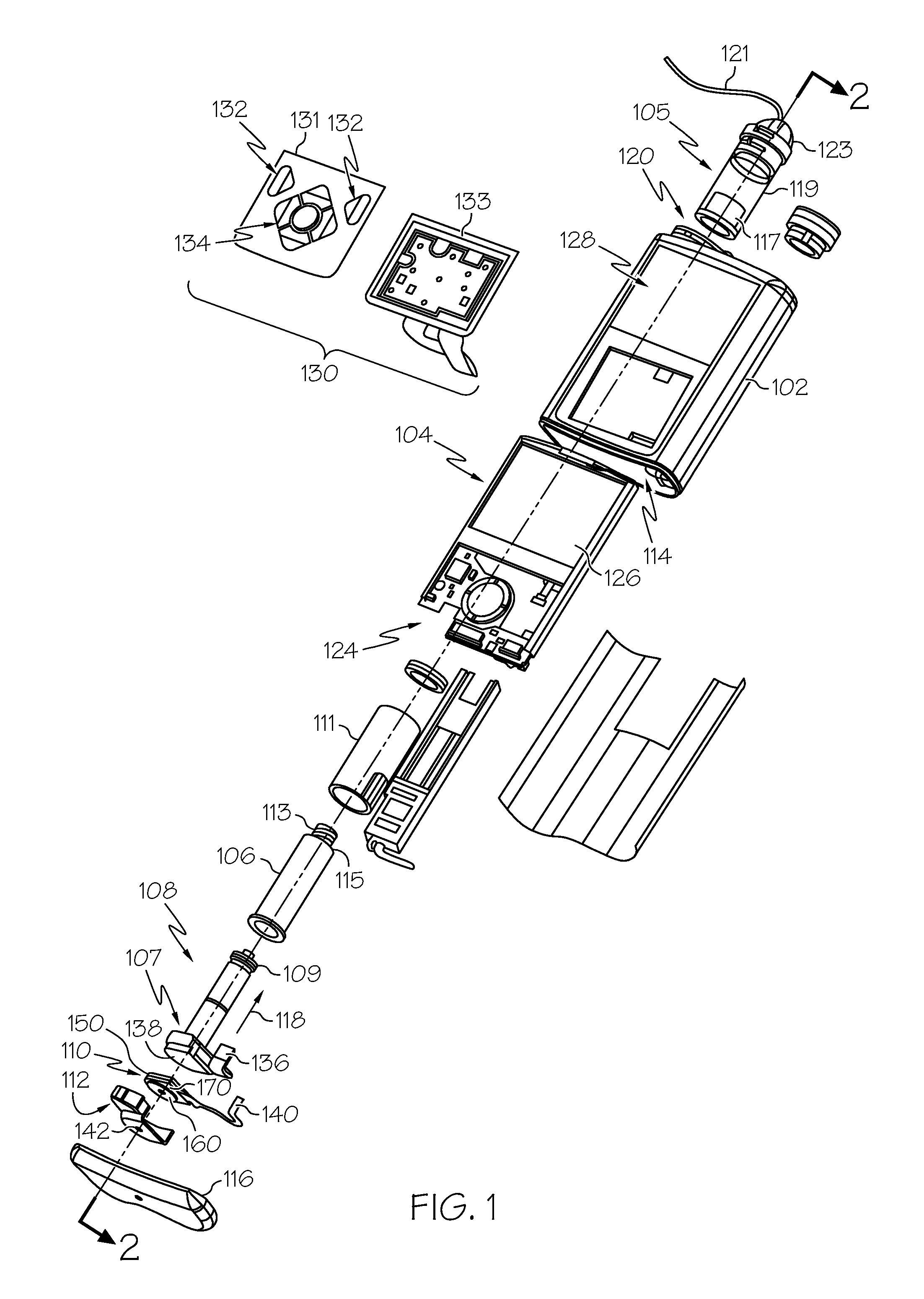
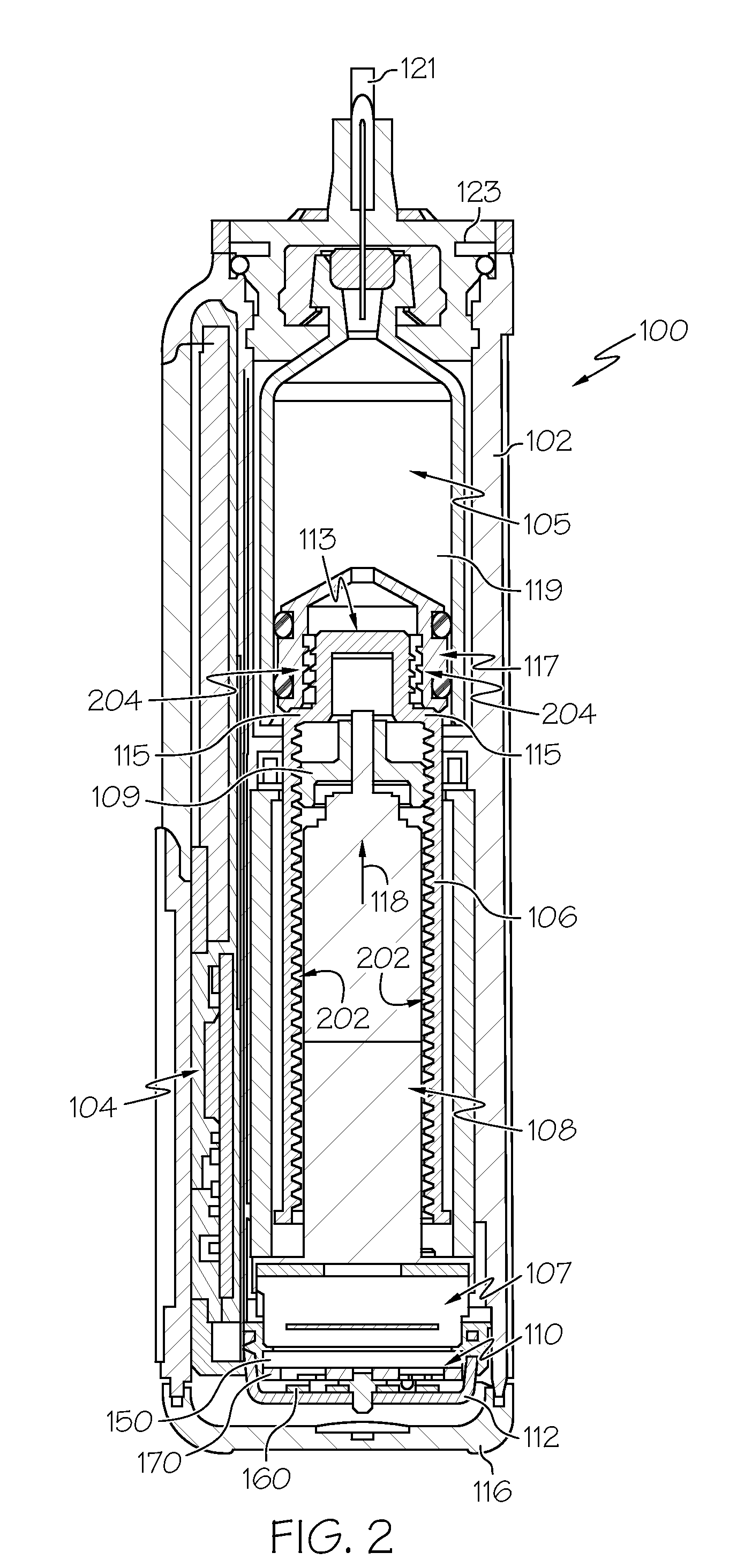
[0036]FIGS. 3-6 depict an exemplary embodiment of a sensor assembly 300 suitable for use as the sensor assembly 110 of FIG. 1. The illustrated embodiment of the sensor assembly 300 includes a back plate structure 350 (also referred to herein as a back plate 350), a loading structure 360 (also referred to herein as a loading element), and a beam structure 370 disposed between the back plate 350 and the loading element 360. The beam structure 370 includes one or more beams 302 mechanically coupled to the loading element 360, such that a compressive force applied to the loading element 360 towards the back plate 350 deflects the beams 302 towards the back plate 350 until the inner portion 318 of the beams 302 contact the back plate 350. Each beam 302 has a sensing element 304 disposed thereon, wherein an electrical characteristic of the sensing element 304 is influenced by the amount of deflection of the respective beam 302, and thus, is indicative of the force applied to the sens...
second embodiment
[0051
[0052]FIGS. 7-8 depict another exemplary embodiment of a sensor assembly 700 suitable for use as the sensor assembly 110 of FIG. 1. The illustrated embodiment of the sensor assembly 700 includes a loading structure 760 (also referred to herein as a loading element), a back plate structure 750 (or back plate), and a beam structure 770 disposed between the back plate 750 and the loading element 760. Various elements of sensor assembly 700 are similar to counterpart elements described above in the context of sensor assembly 300 of FIGS. 3-6, and the common features of such elements will not be redundantly described here in the context of FIGS. 7-8. As described above in the context of FIGS. 3-6, the beam structure 770 includes one or more beams 702 mechanically coupled to the loading element 760, such that a compressive force applied to the loading element 760 towards the back plate 750 deflects the beams 702 towards the back plate 750. Each beam 702 has a sensing element 704 disp...
third embodiment
[0062
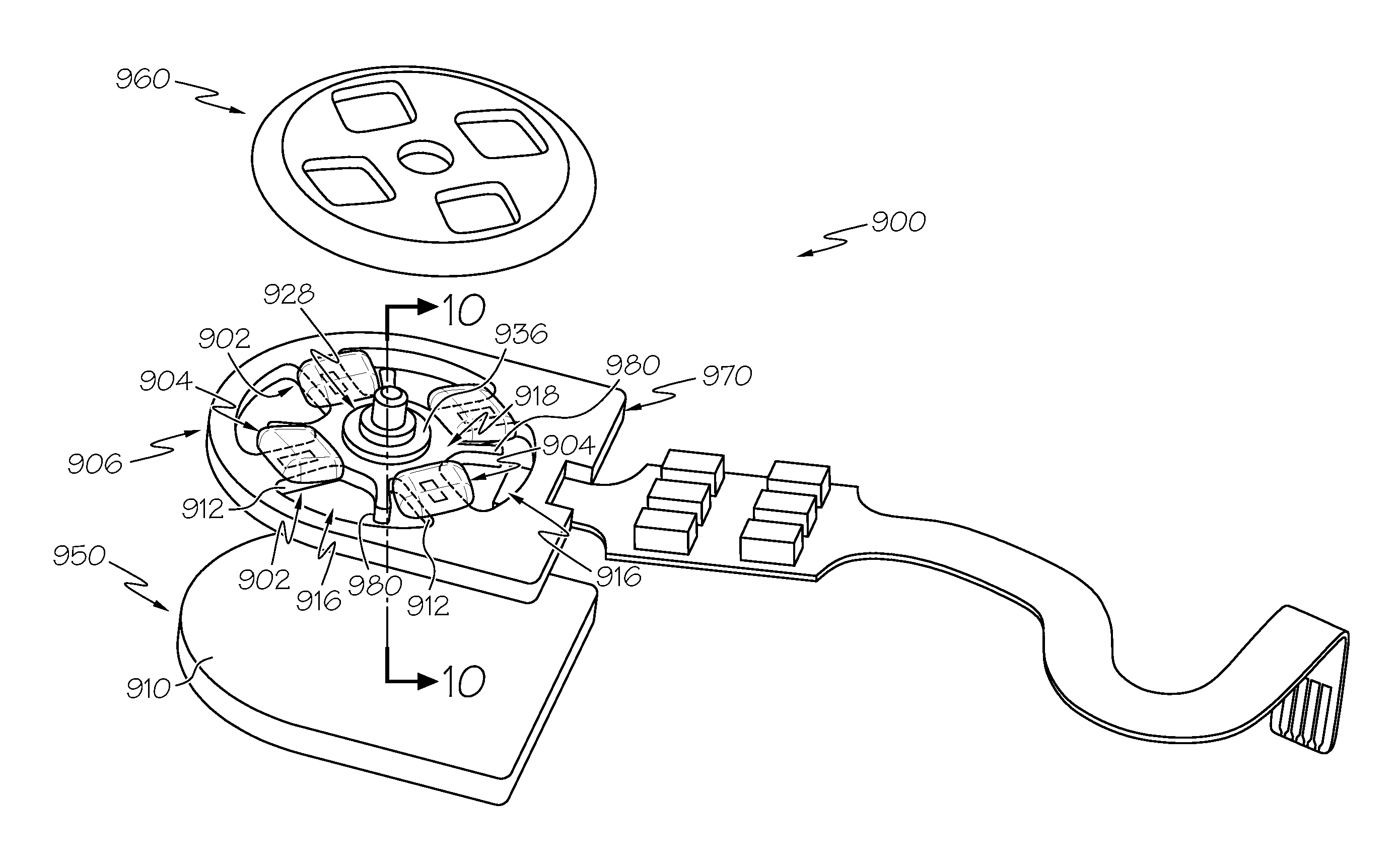
[0063]FIGS. 9-10 depict another exemplary embodiment of a sensor assembly 900 suitable for use as the sensor assembly 110 of FIG. 1. The illustrated embodiment of the sensor assembly 900 includes a loading structure 960 (also referred to herein as a loading element), a back plate structure 950 (or back plate), and a beam structure 970 disposed between the back plate 950 and the loading element 960. Various elements of sensor assembly 900 are similar to counterpart elements described above in the context of sensor assembly 300 of FIGS. 3-6, and the common features of such elements will not be redundantly described here in the context of FIGS. 9-10. As described above in the context of FIGS. 3-6, the beam structure 970 includes one or more beams 902 mechanically coupled to the loading element 960, such that a compressive force applied to the loading element 960 towards the back plate 950 deflects the beams 902 towards the back plate 950. Each beam 902 has a sensing element 904 di...
PUM
| Property | Measurement | Unit |
|---|---|---|
| force | aaaaa | aaaaa |
| displacement | aaaaa | aaaaa |
| translational displacement | aaaaa | aaaaa |
Abstract
Description
Claims
Application Information
 - R&D
- Intellectual Property
- Life Sciences
- Materials
- Tech Scout
- Unparalleled Data Quality
- Higher Quality Content
- 60% Fewer Hallucinations
Browse by: Latest US Patents, China's latest patents, Technical Efficacy Thesaurus, Application Domain, Technology Topic, Popular Technical Reports.
© 2025 PatSnap. All rights reserved.Legal|Privacy policy|Modern Slavery Act Transparency Statement|Sitemap|About US| Contact US: help@patsnap.com


