Suture winding for a drainage catheter

a drainage catheter and suction tube technology, applied in the field of medical devices, can solve the problems of catheters being easily pulled out, hollow caps slipping or being inadvertently removed, and the potential for severe infections

Active Publication Date: 2013-07-30
COOK MEDICAL TECH LLC +1
View PDF31 Cites 16 Cited by
  • Summary
  • Abstract
  • Description
  • Claims
  • Application Information

AI Technical Summary

Problems solved by technology

However, one problem with these catheters is that the catheter may be easily pulled out by body movement, or by emptying of, for example, the bladder.
Another problem is that side ports at the distal end of the catheter may be inadvertently drawn into the abdominal cavity, creating the potential for severe infections.
A problem with this catheter design is that once the protruding first end of the flexible tension member is cut, the hollow cap may slip or be inadvertently removed.
As a result, the shortened flexible tension member moves distally, releases the pigtail, and is either difficult or impossible to retrieve.
Disadvantageously, such devices enlarge the profile of the drainage catheter and require additional connections, thereby complicating the drainage procedure.

Method used


Image

  • Suture winding for a drainage catheter
  • Suture winding for a drainage catheter
  • Suture winding for a drainage catheter

Examples


Embodiment Construction

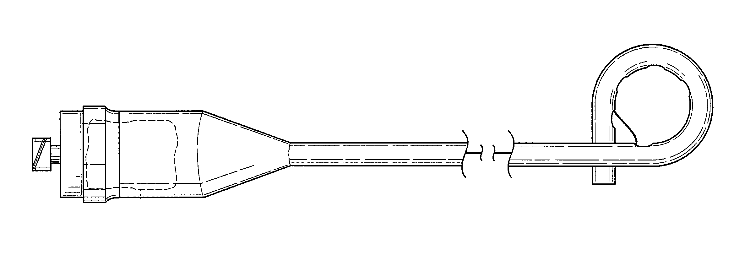
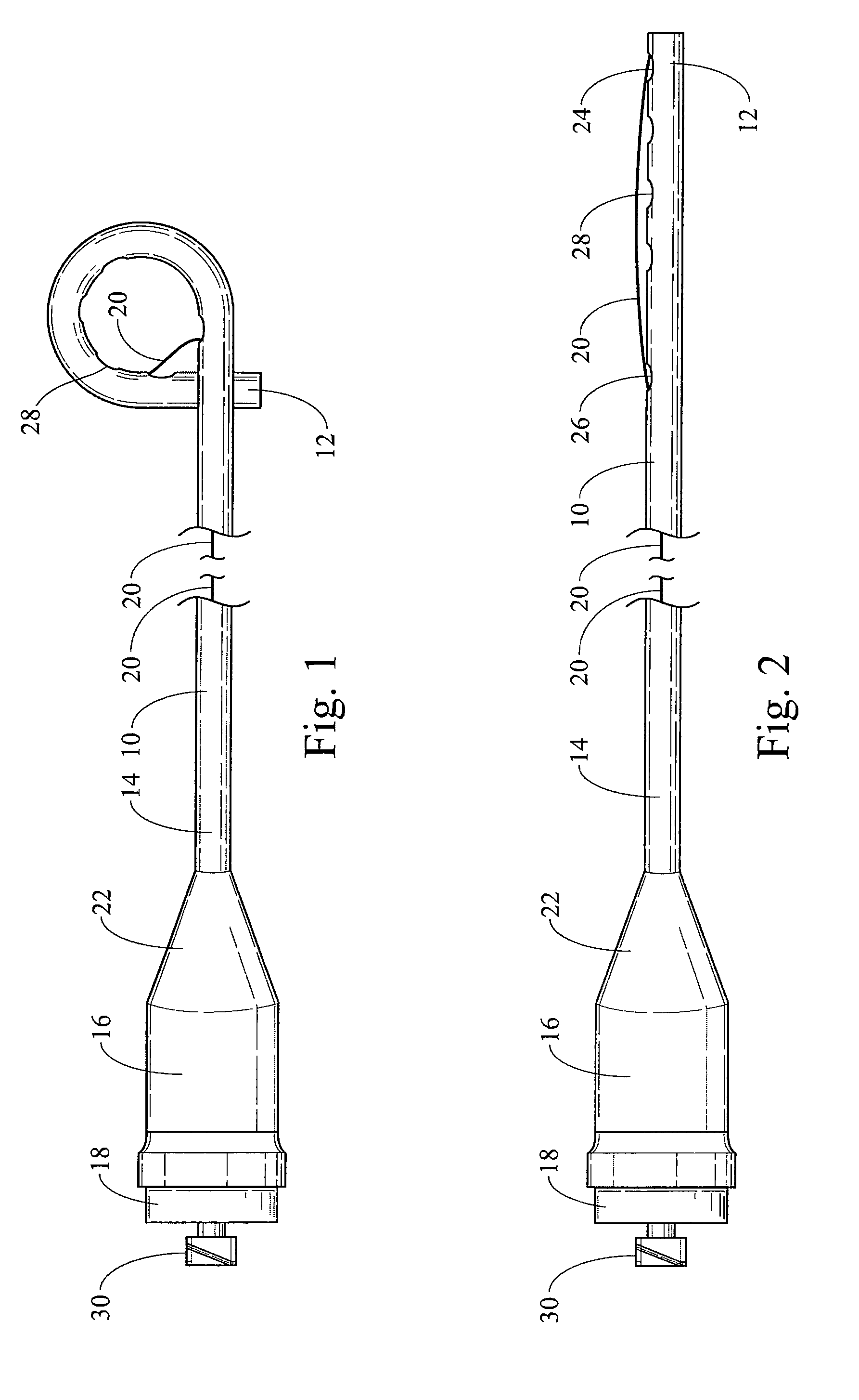
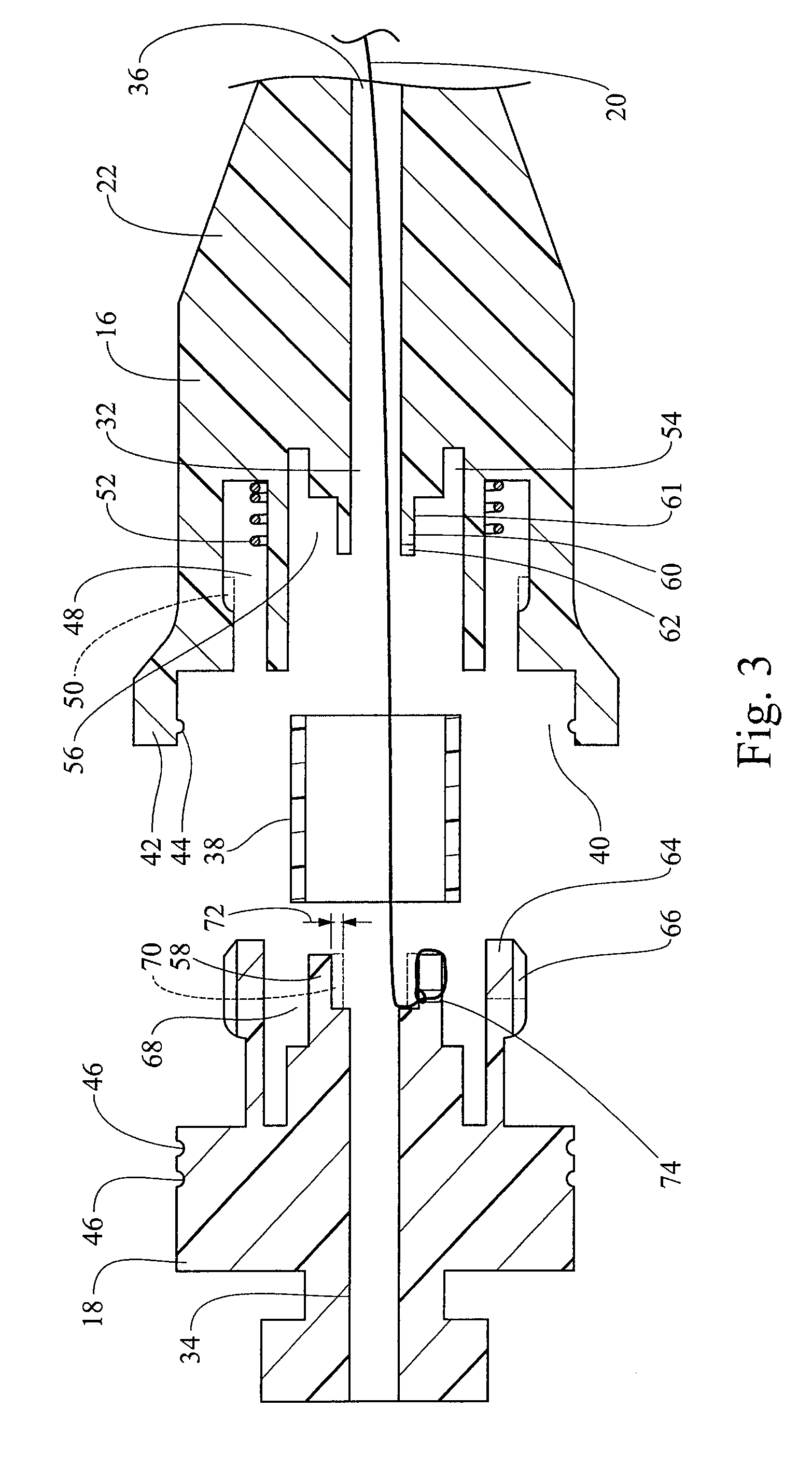
[0022]In accordance with one embodiment of the drainage catheter claimed herein, and as shown in FIGS. 1 and 2, the drainage catheter includes a catheter tube 10 having distal and proximal ends 12, 14, a first connecting piece 16, a second connecting piece 18, and a tension member 20. The proximal end 14 of the catheter tube 10 is attached to the first connector piece 16 at a transitional connection 22. The transitional connection 22 may be accomplished using a ferrule, adhesive, frictional fit, clamps, a threaded connector, or in other manners known to those skilled in the art. In this embodiment, the distal end of the catheter tube includes a distal opening 24. A proximal opening 26 is located proximal of the distal opening 24, i.e., nearer the middle of the catheter tube 10. In some embodiments, a plurality of openings 28 will be arrayed between the distal opening 24 and proximal opening 26. Additional openings may also be placed proximal of the proximal opening 26, or the additi...


PUM


Abstract

Drainage catheters for use in a variety of medical procedures are presented herein. The drainage catheter features an improved tension member locking mechanism. In use, once the drainage catheter is placed as desired, a second connector piece is rotated relative to a first connector piece to wind the tension member around a spooling region and pull the distal end of the catheter tube into a locked configuration. Once the tension member is tensioned, the first and second connector pieces are pulled into a locking engagement thereby securing the catheter tube in the locked configuration.

Description

[0001]This application claims the benefit under 35 U.S.C. §365 as a national application of PCT Application No. US2010 / 022814, filed Feb. 2, 2010, and claims the benefit under 35 U.S.C. §119(e) of U.S. Provisional Application No. 61 / 150,468, filed Feb. 6, 2009, both of which are hereby incorporated by reference herein.TECHNICAL FIELD[0002]The present invention generally relates to medical devices and specifically to medical devices intended for draining fluids from parts of human or animal bodies. In particular, the present invention relates to mechanisms for tightening a tension member used in drainage catheters.BACKGROUND[0003]The present invention relates generally to catheters and particularly to a lockable connector for drawing and maintaining the distal end of a catheter into a desired locked configuration.[0004]Physicians currently use stabilizing structures to immobilize catheters and tubes within various body lumens, including the gastro-intestinal tract and the biliary duc...

Claims


Application Information

Patent Timeline
Patent Type & Authority Patents(United States)
IPC IPC(8): A61M1/00
CPCA61M25/0097A61M25/04A61M27/00A61M2025/0163A61M2210/1085
Inventor EELLS, ROBERT M.EELLS, SCOTT E.
Owner COOK MEDICAL TECH LLC
Why Eureka
Try Eureka