Communication and control of accessories mounted on the powered rail of a weapon
What is AI technical title?
AI technical title is built by Patsnap AI team. It summarizes the technical point description of the patent document.
a technology of communication and control, which is applied in the direction of weapons, butts, firing/trigger mechanisms, etc., can solve the problems of affecting the performance of the weapon, and affecting the choice of the self-contained accessories, so as to reduce the weight of the power-consuming accessories
Active Publication Date: 2013-08-27
T WORX HLDG LLC
View PDF56 Cites 98 Cited by
Summary
Abstract
Description
Claims
Application Information
AI Technical Summary
This helps you quickly interpret patents by identifying the three key elements:
Problems solved by technology
Method used
Benefits of technology
Problems solved by technology
It is a problem to reliably provide electric power to power-consuming accessories which are mounted on a weapon in an environmentally hostile environment.
However, the weight of the batteries in all of the power-consuming accessories creates an imbalance in the weapon and adds a significant amount of weight to the weapon.
That, coupled with the cost of provisioning numerous types of batteries, renders self-contained accessories a poor choice.
The use of electrical contacts mounted on mating surfaces of two elements is optimal for quick connect applications, but these contacts are susceptible to contamination, which degrades performance.
However, the tethering electrical cable and the connector shell are significantly more expensive than the use of electrical contacts mounted on mating surfaces of two elements, although they provide greater protection from the environment, but are also less convenient for quick connect applications.
However, these technologies fail to provide a user with control over the operation of the power-consuming accessories, since they simply provide electrical connection to the power source and must rely on a power switch mounted on each power-consuming accessory to enable the user to apply power in a binary, on / off manner to that power-consuming accessory.
The need to operate such a switch on a power-consuming accessory is inconvenient and prevents the user from having the ability to rapidly power-up and power-down the power-consuming accessory.
In the case of a plurality of power-consuming accessories being mounted on the weapon, such a power control method is cumbersome at best.
Method used
Image
Click on the blue label to locate the original text in one second.
Reading with bidirectional positioning of images and text.
Examples
Embodiment Construction
Definitions
[0024]Contact—One-half of a Contact Pair consisting of an electrically conductive surface which is electrically connected to a power source or power-consuming device.
[0025]Contact Pair—A set of two Contacts which, when brought together in mechanical contact, complete an electrical circuit enabling the transfer of electrical power and / or electrical signals therebetween.
[0026]Visible Spectrum—The visible spectrum is the portion of the electromagnetic spectrum that is visible to (can be detected by) the human eye. Electromagnetic radiation in this range of wavelengths is called “visible light” or simply “light”. A typical human eye responds to wavelengths from about 390 nm to 750 nm. In terms of frequency, this corresponds to a band in the vicinity of 400 THz to 790 THz.
[0027]Electrical Resistivity—Electrical Resistivity is a measure of how strongly a material opposes the flow of electric current. A low resistivity indicates a material that readily allows the movement of ele...
PUM
Abstract
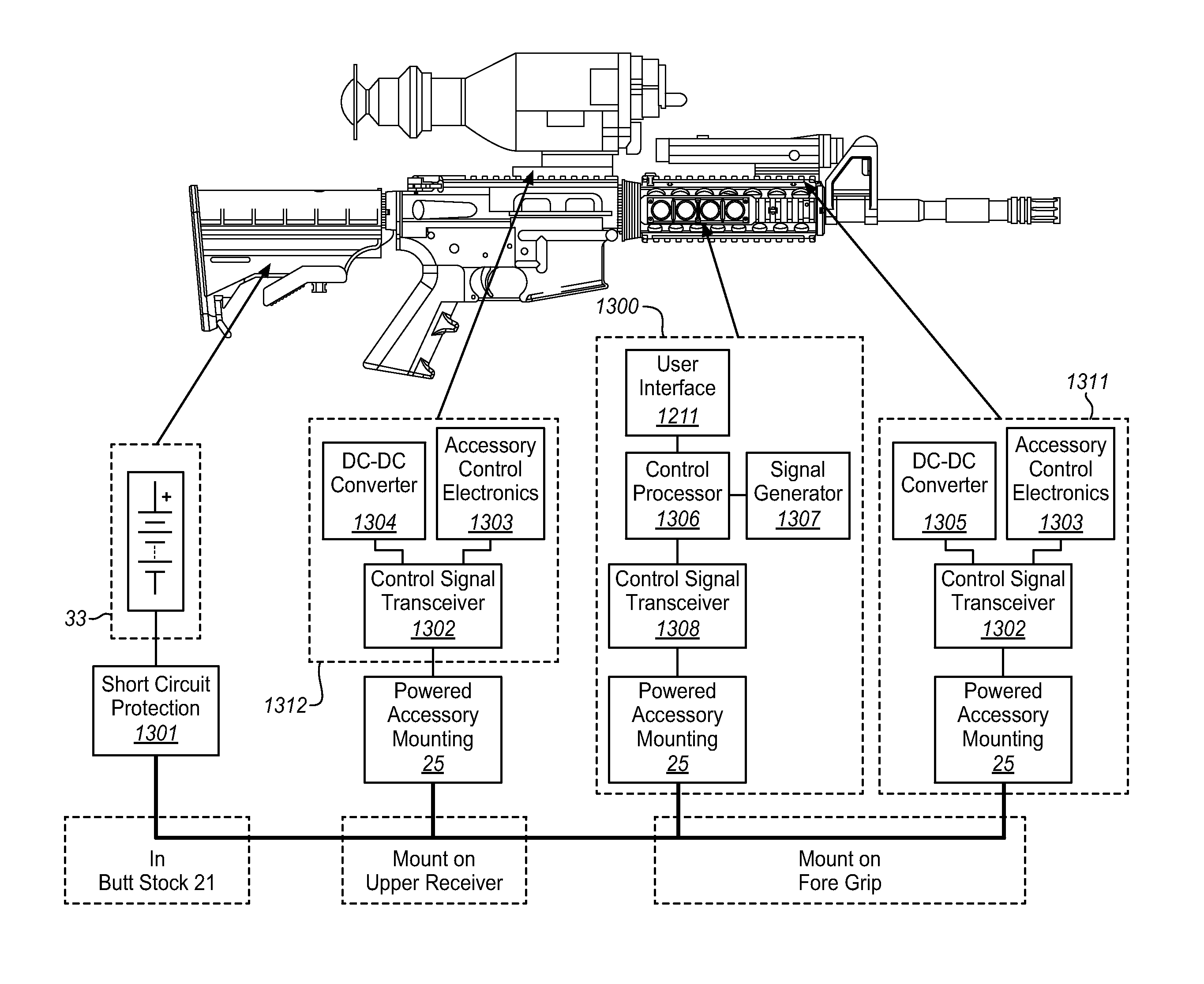
A firearm may have a plurality of power-consuming accessories that can be attached to the weapon. In order to reduce the weight of these power-consuming accessories, as well as the proliferation of their batteries, the Weapon Accessory Power Distribution System provides a common power source to power the power-consuming accessories attached to the weapon. One or more powered rails are provided on the handguard, which encircles the barrel of the weapon, to provide a point of mechanical and electrical interconnection for the power-consuming accessories to provide quick-connect mounting and dismounting of the power-consuming accessory, absent the use of connectors with their tethering cables, which are susceptible to entanglement. The Weapon Accessory Control System is provided to enable the user to control the activation of a power-consuming accessory as well as enable communications between the user and the accessory and among power-consuming accessories.
Description
CROSS-REFERENCE TO RELATED APPLICATIONS[0001]This application is a continuation-in-part of U.S. patent application Ser. No. 12 / 791,460 filed on Jun. 1, 2010, titled “Rugged Low Light Reflectivity Electrical Contact,” which claims the benefit of U.S. Provisional Patent Application Ser. No. 61 / 183,250 filed on Jun. 2, 2009, titled “Non-Reflective, Conductive Mesh, Environmentally Robust Electrical Contacts.” This application is also a continuation-in-part of U.S. patent application Ser. No. 12 / 689,439 filed on Jan. 19, 2010, titled “Rifle Accessory Rail, Communication, And Power Transfer System—Power Distribution,” which claims the benefit of U.S. Provisional Patent Application Ser. No. 61 / 145,228 filed on Jan. 16, 2009; U.S. patent application Ser. No. 12 / 689,430 filed on Jan. 19, 2010, titled “Rifle Accessory Rail, Communication, And Power Transfer System,” which claims the benefit of U.S. Provisional Patent Application Ser. No. 61 / 145,232 filed on Jan. 16, 2009; U.S. patent applica...
Claims
Application Information
Patent Timeline
Application Date:The date an application was filed.
Publication Date:The date a patent or application was officially published.
First Publication Date:The earliest publication date of a patent with the same application number.
Issue Date:Publication date of the patent grant document.
PCT Entry Date:The Entry date of PCT National Phase.
Estimated Expiry Date:The statutory expiry date of a patent right according to the Patent Law, and it is the longest term of protection that the patent right can achieve without the termination of the patent right due to other reasons(Term extension factor has been taken into account ).
Invalid Date:Actual expiry date is based on effective date or publication date of legal transaction data of invalid patent.
Patent Type & AuthorityPatents(United States)
IPC IPC(8): F41A19/00
CPCF41C23/22F41C27/00F41G1/387F41G11/003
InventorCABAHUG, ERIC F.DODD, JAMES S.FELDMAN, BENSCHROEDER, JOHN

