Flow control valves

a flow control valve and proportional technology, applied in mechanical control devices, limiting/preventing/returning movement of parts, instruments, etc., can solve the problems of major interference with the hydraulics or electrical equipment of the vehicle, the operator cannot choose whether to switch the locking device on or off, and the use of quite costly structural parts, etc., to achieve the effect of reducing manufacturing and assembly costs, simplifying the change-over of the attachment, and reducing the cost of operation

Inactive Publication Date: 2013-08-27
AGCO GMBH
View PDF14 Cites 0 Cited by
  • Summary
  • Abstract
  • Description
  • Claims
  • Application Information

AI Technical Summary

Benefits of technology

[0012]The structural parts needed for the device are simple, mechanical components of low manufacturing and assembly cost, which can be fitted if necessary to existing vehicle-borne valves. By using the existing vehicle-borne valves the operator controls of the valves fitted in the cab can also be used, whereby the operation of different attachments is standardized and the costs of operating these attachments can be kept to a minimum. In addition, the device can be retrofitted in simple way without interfering with the valve itself or with the pressure circuit. This is very advantageous if the operational use of the agricultural tractor is changed by fitting other attachments and the device is not always or is no longer required. Moreover, with each attachment the operator can decide himself whether the locking device is necessary and very simply to switch this on or off and therefore to control several attachments with one hydraulic valve.
[0013]As a result the possible applications of an agricultural tractor, which is equipped with this device, are substantially increased and the change-over of attachments simplified for the operator. This leads to more economic use of the agricultural tractor.

Problems solved by technology

Deliberate switching of the locking device on or off by the operator is not possible as a result.
Although a device can be derived from these solutions, in which the locking can be deliberately switched on or off, this requires purely hydraulic or electrohydraulic control of a locking device and thus the use of quite costly structural parts.
Moreover, major interference with the vehicle hydraulics or electrical equipment is necessary for retrofitting or for optional installation of such a locking device.
Sometimes commercial valves cannot be used for installing this locking function and have to be replaced by valves which must be adapted for installing the locking device and are therefore substantially more expensive.

Method used


Image

  • Flow control valves
  • Flow control valves
  • Flow control valves

Examples


Embodiment Construction

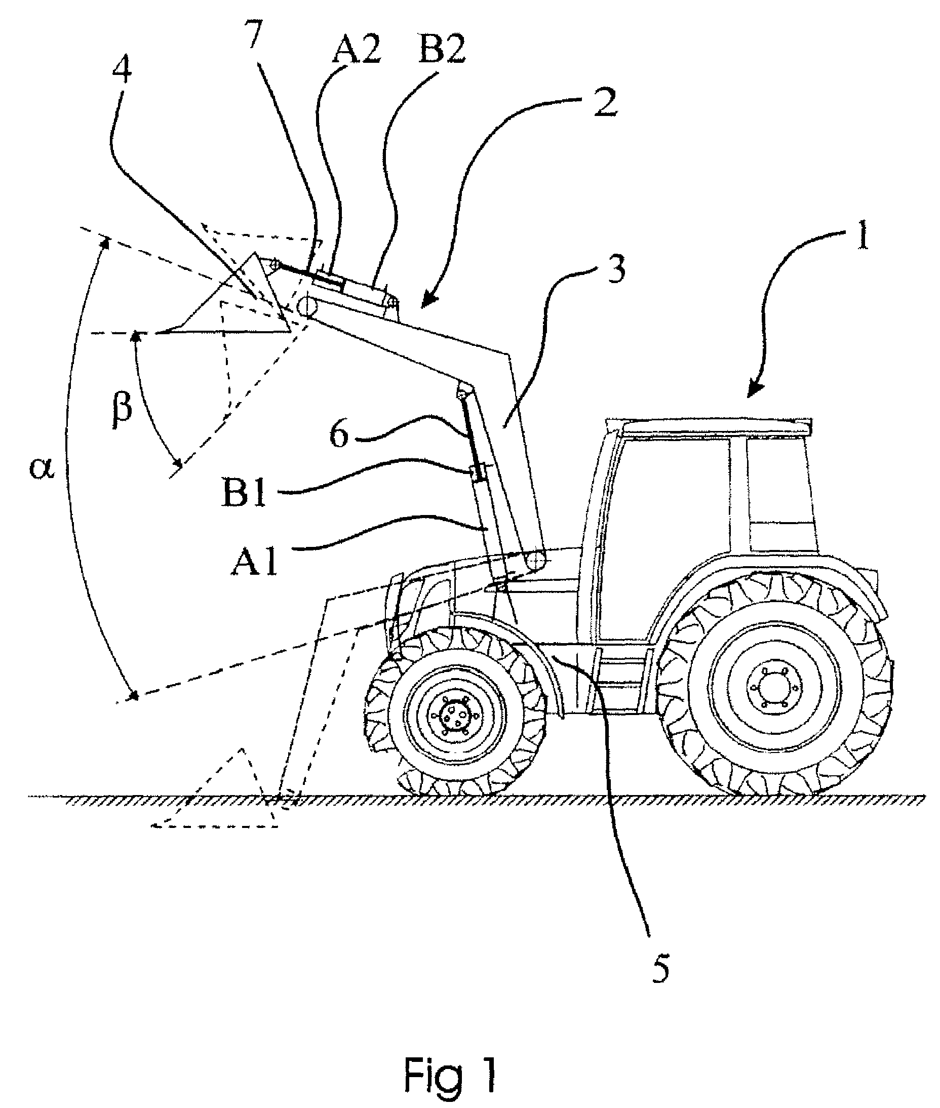
[0021]FIG. 1 shows an agricultural tractor 1 on which a front loader 2 is mounted. The front loader basically consists of front loader arms 3 and a front loader attachment 4. The front loader arms 3 are rotatably connected to the chassis 5 of the agricultural tractor 1 in the plane of projection. So that the front loader arms 3 can pivot, each arm has a hydraulic cylinder 6, which has two cylinder chambers A1, B1 connected between the vehicle chassis 5 and the arm 3. The stroke of the operating cylinders 6 for the front loader arms 3 and therefore the pivoting angle α of the front loader arms 3 is controlled by the supply and discharge of the pressure in the cylinder chambers A1 and B1.

[0022]The front loader attachment 4 (here illustrated as a bulk material shovel) is rotatably connected to the front loader arms 3 in the plane of projection. So that the front loader attachment 4 can pivot relative to arm 3, an operating cylinder 7, which has two cylinder chambers A2, B2, is connecte...


PUM


Abstract

A mechanically operated proportional flow control valve (8) which a valve spool (9) is described, which is moveable between two end limits limiting a regulating range. A device (20, 22) is described for selectively limiting the regulating range of the valve (8). This device can be used to block “locked-in” positions (F1, RH1) of the spool (9) at the end limits of the regulating range. The device includes a locking bar 20 which has locking formations (28, 29) which engage a pin (22) on a lever (11) connected with the spool (9).

Description

[0001]This application is based on, and claims the benefit of priority to, UK application GB 0616168.1, filed 15 Aug. 2006, which priority application is hereby incorporated by reference.BACKGROUND OF THE INVENTION[0002]1. Field of the Invention[0003]The invention relates to a mechanically operated proportional flow control valves with a valve spool movement which has a non-indexed regulating range, a neutral position, which is automatically assumed if the actuating force applied to the spool is released, and at least one so-called “locked in” position at one at least of the two end limits of the regulating range in which the spool is locked in a fixed position. Hereinafter such a valve is referred to as “a valve of the type described”.[0004]In agricultural operations a variety of attachments are used for different work. Each of these pieces of equipment makes individual demands on the vehicle-borne hydraulics and in particular on the functions of the vehicle-borne hydraulic valves ...

Claims


Application Information

Patent Timeline
Patent Type & Authority Patents(United States)
IPC IPC(8): F16K35/00
CPCF16K11/0704F16K35/025Y10T74/20678Y10T137/7069F16K35/00
Inventor DIETRICH, ULRICHKNOBLOCH, JURGEN
Owner AGCO GMBH
Why Eureka
Try Eureka