Heat pumps, however, have operating limitations compared to traditional fossil-fired heating equipment with respect to temperature of the delivered heat.
This is a significant limitation when applying
air source heat pumps to existing buildings having
heat distribution systems that were designed for use with traditional fossil fueled heating boilers.
Using a heat pump to completely replace an existing boiler can be a challenge because, at the lower
water temperature that can be produced by the heat pump, there may not be a sufficient amount of heat delivery capacity (so-called “
radiation”) to heat the building during very cold outdoor temperatures.
Another
disadvantage to currently available heat pump systems as replacements for traditional fossil fueled boilers, in addition to the supply temperature problem, is that the heating capacity and the efficiency of heat pumps decreases significantly at low outdoor temperatures of about 0 F compared to their heating capacity and efficiency at a 40 F
outdoor temperature.
Thus, the size of the heat pump unit needed to meet
cold weather conditions can be large, even though it operates most of the time in more moderate
outdoor temperature conditions.
Depending on the heat pump's operating characteristics, the heat pump in such a
combination system may not operate at all during very low outdoor temperature conditions.
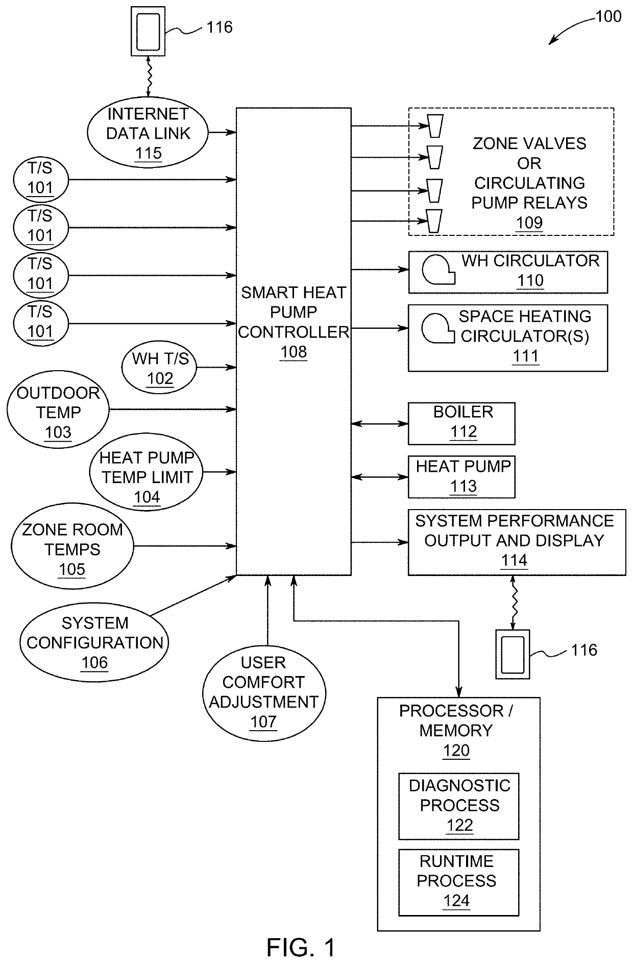
The challenge in applying a heat pump in combination with a fossil-fuel fired boiler involves several issues, especially recognizing that such forced hot
water heating systems may be composed of a number of heating zones, each separately controlled by a
thermostat in each separate zone.
The fundamental issue is achieving most
beneficial use of the heat pump with its supply
water delivery temperature limitation and outdoor-temperature-dependent operating efficiency.
This is a complex control problem and, to date, there have been no commercially available products that are specifically designed to meet the control challenge of such combined systems.
Part of the challenge of achieving optimum design and control of such a combined heat pump and fuel-fired boiler
system, especially when applied to an existing building with an existing
heat distribution system that was originally deployed with a
fossil fuel fired boiler, is that there is usually poor understanding of the capacity of the existing
radiation system to deliver the required amount of heat for that particular zone given the
heat supply temperature limits of a heat pump.
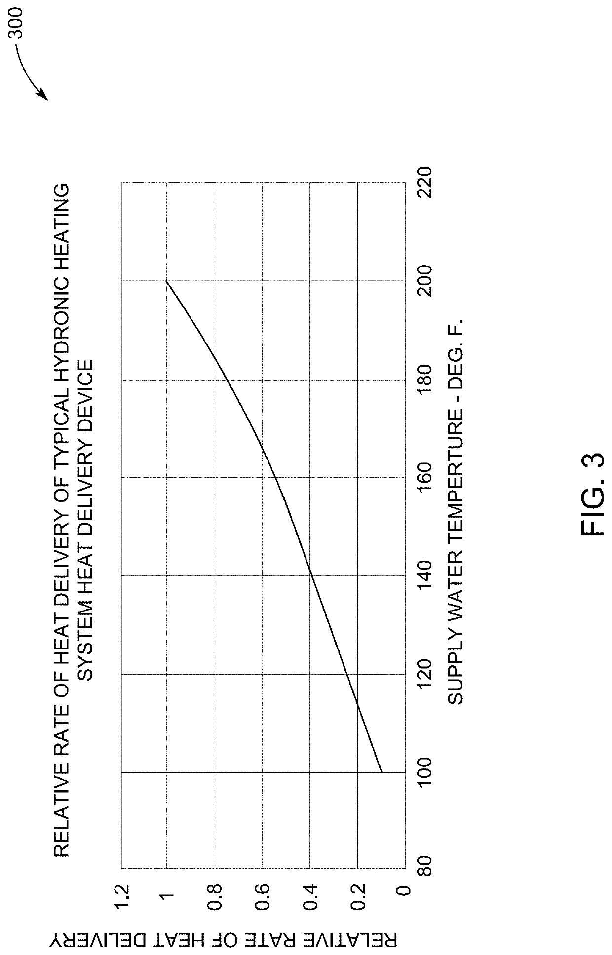
While presumably all zones in any existing system originally deployed with a fossil fueled boiler having relatively
high heat delivery temperature, for example 180 to 200 F, can satisfy, in reasonable time, the heating demands for all zones under all weather conditions, it is not easy to determine, by inspection, how well a zone might function with the lower heat delivery temperature of a heat pump.
Thus, by simple inspection of an existing
heating system it is very difficult to predict the performance of a heat pump added in combination with a fossil-fueled boiler for an existing
heating system.
It can be uncertain as to what comprises the preferred
control logic relative to zone heating demands with the limited information about the existing radiation system without performing detailed analysis of both heat loads in each zone and the performance characteristics of the existing heat dissipation devices, such as
baseboard radiator and panel heaters, in each zone.
Accordingly, the application of heat pumps to existing hydronic heating systems designed for use with fuel-fired boilers has been limited and, when done so, has been performed in a manner that can result in poor utilization of the heat pump, poor comfort control, poor operating economy, low environmental benefits, over- or under-sized heat emitters and other excessive equipment costs.
This stems from the practical need to make very conservative design assumptions about the existing radiation system and its ability to function with the lower supply temperature of the heat pump.
Installers of heating systems dread the future compliant that the new heating system they have installed for a customer does not provide the desired
thermal comfort, so the inclination is to specify more, and oversized, equipment that is not actually necessary or cost justified.
This has always been a well-known, and often justified, inclination of the sellers and installers of the heating system, but in the case of heat pump systems these inclinations can have even greater negative impacts on equipment costs, installation costs, and system operating costs.
The fact that there are usually several heating zones in an existing system, each operating independently and each having its own heat dissipation characteristic, only further complicates the efficient deployment of heat pumps in combination with fuel-fired boilers, especially in existing building with existing radiation systems.
A further complication in the application of heat pumps in conjunction with boilers is that, in many if not most cases, simultaneous operation of a heat pump and boiler will not be possible without major
heat distribution system redesign and rebuild.
Thus, it is not (typically) possible to operate a heat pump with say a 130 F supply
temperature limit simultaneously with a boiler operating at a 180 F operating supply temperature (and say a 160 F return temperature).
A complex mechanical and control scheme is theoretically possible to allow such simultaneous operation, but cost may be prohibitive.

