Dental implant bar system

a dental implant and adjustable technology, applied in dentistry, dental surgery, medical science, etc., can solve the problems of additional production delays and costs, the amount of fabrication time is required, and the delivery delay can be up to several weeks

Inactive Publication Date: 2013-09-03
ALLAIRE ERIC
View PDF22 Cites 2 Cited by
  • Summary
  • Abstract
  • Description
  • Claims
  • Application Information

AI Technical Summary

Benefits of technology

[0013]Embodiments of the present invention provide a dental prosthesis which can be adjusted and which may have articulated and telescopic arms and a dental implant bar which can be secured to implant heads already installed in the patient's mouth or alternatively on a manufactured model made with computerized surgical simulation software or using a conventional dental printing system with transfers. The bar, once adjusted by the dentist, will be integrated in the manufacturing process of an implant support prosthesis.

Problems solved by technology

One of the problems of conventional dental implant bars is the amount of time required for fabrication.
The use of a lab to fabricate or cast this type of structure is generally required and thus one may encounter delivery delays of up to several weeks.
Moreover, conventional dental implant bars, being fabricated and assembled prior to installation, may be entirely unusable or require considerable modifications if errors occur during the manufacturing process, thus causing additional production delays and costs.
The manufacturing of such dental implant bars is generally sub-contracted offsite, increasing costs, delays and risk of error.

Method used


Image

  • Dental implant bar system
  • Dental implant bar system
  • Dental implant bar system

Examples


third embodiment

[0070]According to the present invention, referring now to

[0071]FIGS. 26 to 35, the arm assembly 16 may comprise a first arm segment 104 and a second arm segment 106, which are slidably engaged in a telescoping cooperation and project from opposite extremities 18 of the arm assembly 16. The first arm segment and / or the second arm segment may have a threaded aperture extending transversally therein, for receiving a set screw, namely to frictionally lock or to adjust the position of the first arm segment with respect to the second arm segment, similarly to the arm assembly according to the first and second embodiments.

[0072]With respect to the connection between of the arm assembly and the implant bar units, the extremity(ies) of each connecting arm assembly is preferably retained by being sandwiched between the implant socket and the compression assembly.

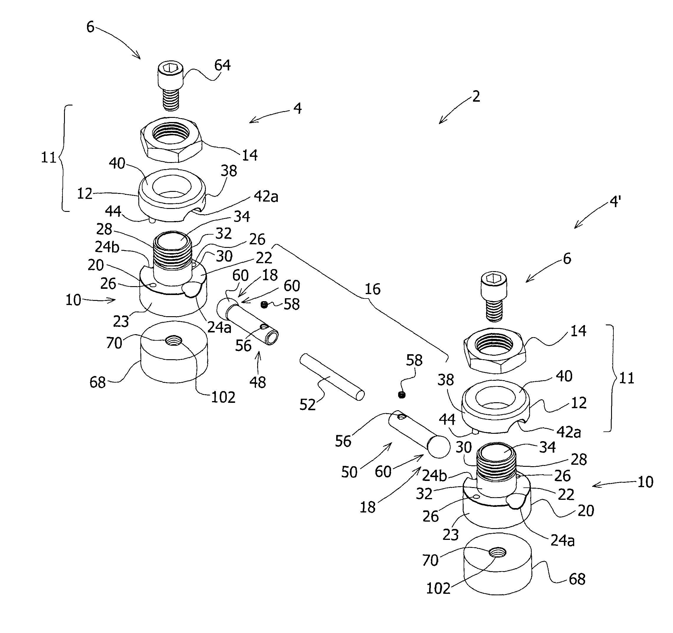
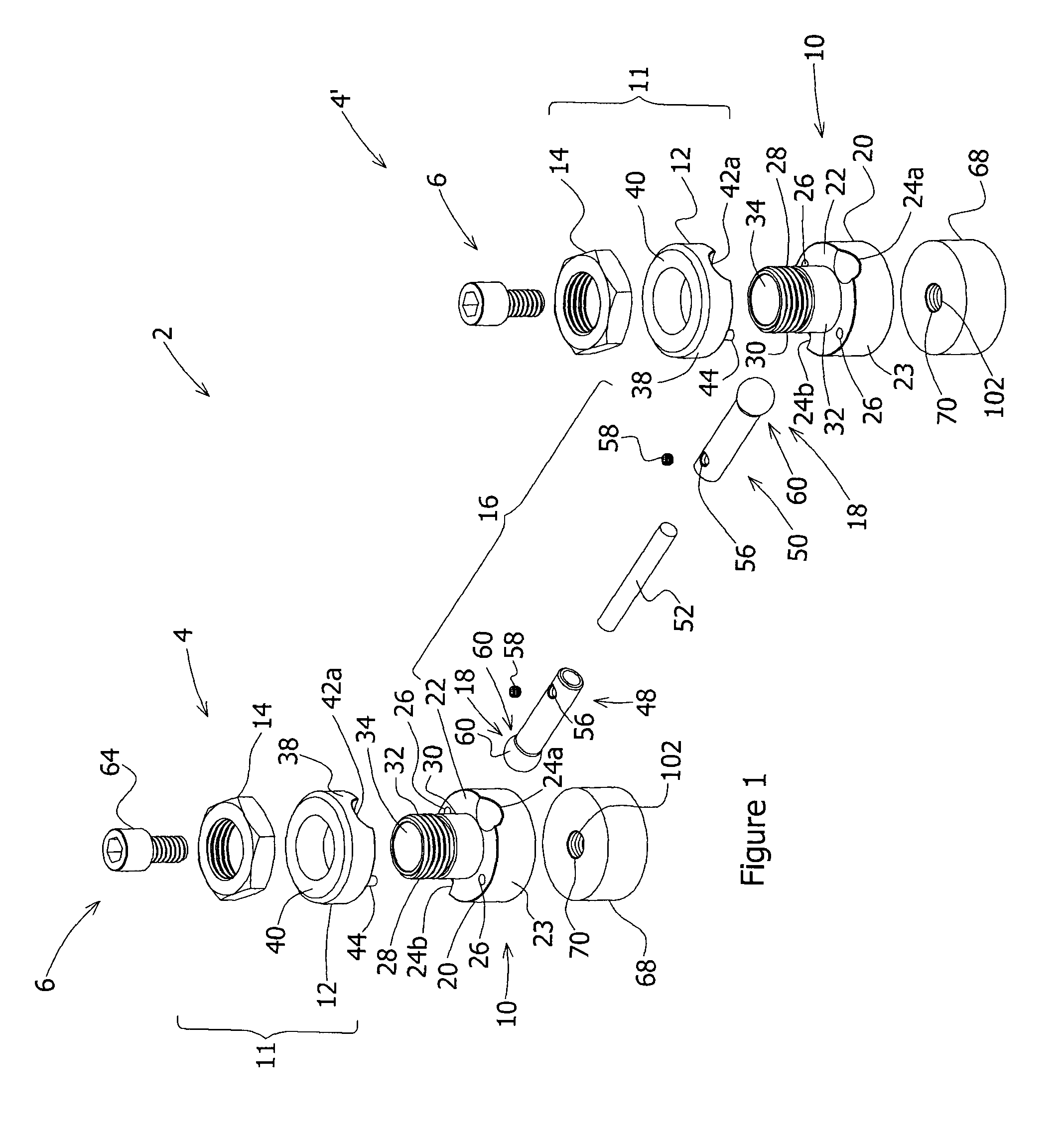
[0073]For example, in the illustrated embodiment of FIG. 1, the spherical extremity 60 of the first arm segment 48 is designed to f...

second embodiment

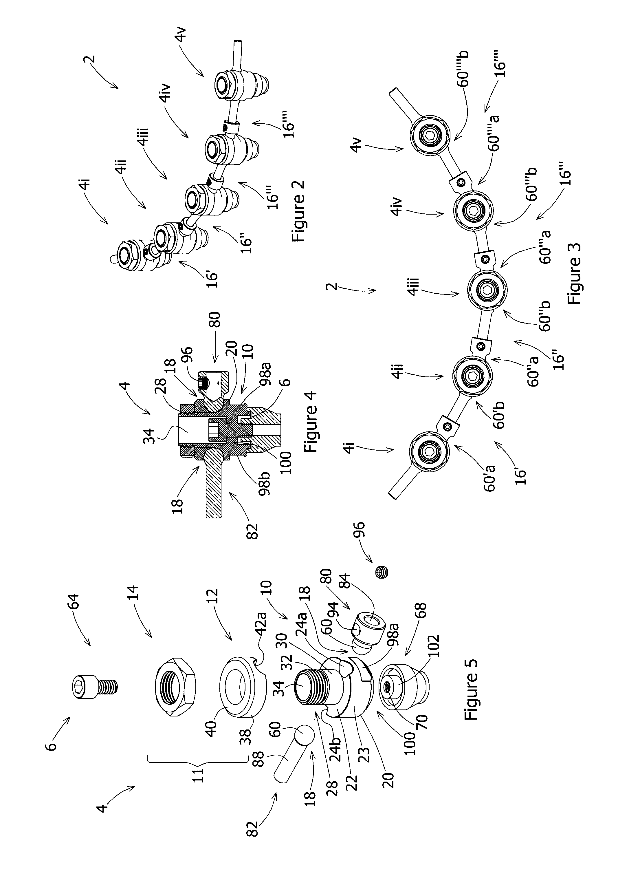
[0075]According to the present invention and referring now to FIG. 5, sphere-shaped extremity 60 of the sleeve 84 is similarly designed to fit within semispherical recesses formed by recesses 24 and 42 of the implant bar unit 4. The sleeve 84 is further shaped and sized to receive extension 88 of a complementary ball pivot arm 82. The sphere-shaped extremity 60 of the complementary ball pivot arm 82 is also adapted to fit with semispherical recesses 24 and 42 of another implant bar unit. The threaded aperture 94 is designed to receive a screw 96 for securing the extension 88 in place.

[0076]Referring back to FIGS. 26 to 35, the extremities 18 of each arm assembly 16 may have a substantially annular shape 108, i.e. ring-shape. Preferably, the extremities 108 of the arm assemblies 16 and the upper wall 22 of the base 20 of each implant socket 10 have mating curved profiles, in order to allow rotational movement of the arm assembly 16 when the compression assembly 11 is configured in a ...


PUM


Abstract

The present invention relates to an adjustable dental implant bar system. There is provided a dental implant bar which can be adjusted and which may have articulated and telescopic arms and which can be further secured to implant heads already installed in the patient's mouth or alternatively on a manufactured model made with computerized surgical simulation software or using a conventional dental printing system with transfers.

Description

CROSS REFERENCE TO RELATED APPLICATIONS[0001]This application claims the benefits of U.S. provisional application for Patent No. 61 / 148,074 filed on Jan. 29, 2009, which is herein incorporated by reference.FIELD OF THE INVENTION[0002]The present invention relates to an adjustable dental implant bar system.BACKGROUND OF THE INVENTION[0003]Known in the art are dental implant bars and related devices. Dental implants are generally used to provide a base or support for a prosthesis. The implants are placed in the jawbone and act as an anchor point for various dental prosthetic devices. Often, two or more implants are connected together by a dental implant bar, the bar in turn being connected to the dental prosthetic device. Known in the art are, for example, Patent and Patent Application documents No. CA2592538, U.S. 20070190475, DE20221475, SE200402427, U.S. Pat. No. 6,692,254, U.S. 20030108845, NL1017284, U.S. Pat. No. 5,975,904, DE19748268, U.S. Pat. No. 5,885,078, U.S. Pat. No. 5,63...

Claims


Application Information

Patent Timeline
Patent Type & Authority Patents(United States)
IPC IPC(8): A61C8/00
CPCA61C8/0048A61C8/005A61C8/0074A61C13/275A61C8/0068
Inventor ALLAIRE, ERIC
Owner ALLAIRE ERIC
Why Eureka
Try Eureka