Airspeed sensing system for an aircraft

a technology of airspeed sensor and aircraft, which is applied in the direction of vehicle position/course/altitude control, process and machine control, instruments, etc., can solve the problems of reducing the aircraft's performance, reducing accuracy, and airspeed sensors reporting less accurate than desired airspeeds

Active Publication Date: 2013-09-03
THE BOEING CO
View PDF7 Cites 30 Cited by
  • Summary
  • Abstract
  • Description
  • Claims
  • Application Information

AI Technical Summary

Problems solved by technology

The ice may cause the airspeed sensors to report an airspeed for the aircraft that is less accurate than desired.
With a decreased accuracy in detecting the airspeed of an aircraft, the data reported by the sensor systems to a pilot and / or onboard computer systems by the sensor system may reduce the performance of the aircraft.
If the airspeed is not as accurate as desired, control of the airplane may become compromised.

Method used


Image

  • Airspeed sensing system for an aircraft
  • Airspeed sensing system for an aircraft
  • Airspeed sensing system for an aircraft

Examples


Embodiment Construction

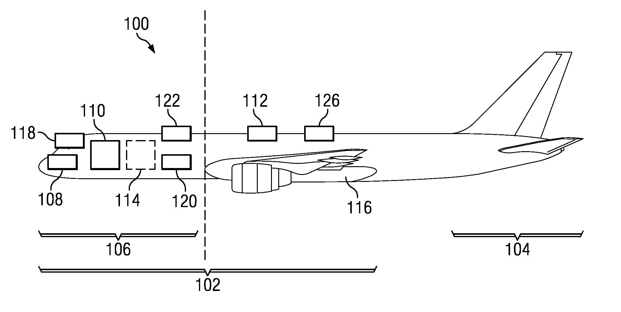
[0025]Looking now to the figures, and with specificity to FIG. 1, an illustration of an aircraft is depicted in accordance with an advantageous embodiment. Aircraft 100 is an example of an aircraft in which advantageous embodiments may be implemented.

[0026]Aircraft 100 is made up of fuselage section 102 and tail section 104. Fuselage section 102 is the main body of aircraft 100 that contains the passengers and crew onboard aircraft 100. Fuselage section 102 also contains flight data processing system 114.

[0027]Fuselage section 102 also contains forward section 106. Forward section 106 is an area of fuselage section 102 located forward of wing 116. Forward section 106 contains cockpit 118, and flight data processing system 114.

[0028]Forward section 106 also contains airspeed sensor systems 108, 110, 112, and 120. In these examples, airspeed sensor system 108 consists of pitot-static probes, and airspeed sensor system 110 consists of angle of attack sensors. Airspeed sensor system 112...


PUM


Abstract

The different advantageous embodiments provide an apparatus and method for identifying an airspeed for an aircraft. In one advantageous embodiment, an apparatus is provided. The apparatus consists of a plurality of pitot-static probes. The plurality of pitot-static probes generate a first data. The apparatus also consists of a plurality of angle of attack sensor systems. The plurality of angle of attack sensor systems generate a second data. The apparatus also consists of a plurality of light detection and ranging sensors. The light detection and ranging sensors generates a third data. The apparatus also consists of a signal consolidation system configured to detect errors in the first data generated by the plurality of pitot-static probes, the second data generated by the plurality of angle of attack sensor systems, and the third data generated by the plurality of light detection and ranging sensors.

Description

BACKGROUND INFORMATION[0001]1. Field[0002]The present disclosure relates generally to sensor systems and more specifically to airspeed sensor systems.[0003]2. Background[0004]Sensor systems for aircraft provide flight data to pilots. These sensor systems provide data such as altitude, airspeed, heading, and pitch to pilots to enable them to operate the aircraft. For example, pilots may use heading data to determine when the aircraft is traveling in the direction of the destination of the aircraft.[0005]The sensor systems are also used by computer systems that control systems onboard the aircraft. For example, airspeed may be used by computer systems onboard the aircraft to control the speed and stability of the aircraft.[0006]True airspeed is the actual speed of an aircraft relative to the air in which the aircraft is flying. Calibrated airspeed is the speed of the aircraft as identified by sensor systems onboard the aircraft. Calibrated airspeed differs from true airspeed in that c...

Claims


Application Information

Patent Timeline
Patent Type & Authority Patents(United States)
IPC IPC(8): G01P5/14
CPCG01P13/025G01P5/16
Inventor MCINTYRE, MELVILLE DUNCAN WALTER
Owner THE BOEING CO
Why Eureka
Try Eureka