Solar window shade

a technology for solar energy and window coverings, applied in sunshades, door/window fittings, constructions, etc., can solve the problems of affecting the view of the occupant through the window, affecting the effect of the remaining hours of the day, and affecting the occupant's view, etc., to achieve the effect of minimizing the amount and maximizing the diffuse ligh

Inactive Publication Date: 2013-09-10
MURPHY FARRELL DEV L
View PDF48 Cites 33 Cited by
  • Summary
  • Abstract
  • Description
  • Claims
  • Application Information

AI Technical Summary

Benefits of technology

[0019]Briefly described, and in accordance with one preferred embodiment thereof, the present invention relates to an apparatus for shading windows of a building from the sun, and including an awning frame pivotally connected at one of its ends to the exterior of the building; the awning frame pivots about a substantially horizontal axis above the top of the window. A frame drive system is supported by the building and is coupled to the awning frame to selectively cause the opposing second end of the awning frame to pivot upwardly or downwardly in accordance with the position of the sun. A number of rotatable louvers are supported at the second end of the awning frame; a louver drive system is supported, at least in part, by the awning frame for selectively rotating the louvers in accordance with the position of the sun. In this embodiment, the pivotal movement of the awning frame, and the rotation of the louvers, tracks daily and seasonal movements of the sun to block direct rays of sunlight, while maximizing passage of indirect light rays for lighting the interior of the building.
[0026]Alternatively, selected surfaces of the louvers may be made reflective. Those surfaces that generally face the window can then reflect indirect light back toward the window. Also, by making the outer surfaces of the inner louvers reflective, rays of light intercepted by such inner louvers can effectively be bounced off of the inner surfaces of the outer louvers back toward the window, particularly if the inner surfaces of the outer louvers are also reflective.
[0030]To maximize blockage of incoming direct rays of the sun while maximizing passage of indirect light into the window, the sum of the first offset arm distance D1 and the second offset arm distance D2 is preferably greater than the aforementioned separation distance S. Ideally, the sum of D1 and D2 only slightly exceeds distance S to minimize interference between adjacent louvers when the sun is incident from a sharp angle relative to the window. To simplify construction, D1 and D2 are preferably equal to each other. However, it is also possible to reduce one of such offsets effectively to zero, e.g., by making the pivot axes of the outer louvers coincident with the longitudinal panel axes of such outer louvers (hence, D1 equals zero), and increasing the offset arm distance D2 for the inner louvers to be slightly in excess of separation distance S. Alternatively, it is possible to make the pivot axes of the inner louvers coincident with the longitudinal panel axes of such inner louvers (hence, D2 equals zero), and to increase the offset arm distance D1 for the outer louvers to be slightly in excess of separation distance S.
[0031]As before, the width of the outer louvers and the width of the inner louvers is preferably kept constant at value W to maximize the view. To insure blockage of direct rays of the sun, width W is preferably greater than the separation distance S which separates the pivot axis of each inner louver from the pivot axes of each of the adjacent preceding and succeeding outer louvers. It is preferred that width W only slightly exceed separation distance S to minimize interference between adjacent louvers when the sun is at a sharp angle relative to the window.
[0032]Alternatively, different widths W1 and W2 may be used for the outer louvers and inner louvers, respectively. In that case, the sum of the widths W1 and W2 is preferably greater than twice the separation distance S which separates the pivot axis of each inner louver from each of the pivot axes of the adjacent preceding and succeeding outer louvers. Again, it is preferred that the sum of the widths W1 and W2 only slightly exceed twice the value of separation distance S to avoid interference between adjacent louvers.
[0034]As was true of the earlier-described embodiments, a photovoltaic panel may be provided upon the outer surface of one or more of the outer louvers, generally facing away from the window of the building, to generate electrical power. As was also described earlier, the outer and inner louvers may have selective surfaces that maximize the diffuse light within the visible spectrum which is reflected into the window while reducing the maximum temperature attained by the louvers and minimizing the amount of light within the infrared spectrum that radiates toward the window.

Problems solved by technology

While those skilled in the art have proposed a number of different shade devices for blocking the passage of excess sunlight through a window, the majority of such prior attempts are inefficient and / or objectionable.
For example, while some known shade devices may be effective in blocking the passage of sunlight through a window into the interior space of a home or commercial building, they also interfere with an occupant's view through the window.
Still other known shade devices may be effective at shading direct sunlight during certain hours of the day, or during certain seasons of the year, but lose their effectiveness during the remaining hours of the day, or during the remaining seasons of the year.
Other known shade devices require extensive modification of existing windows within a building, or are otherwise complex and expensive.

Method used


Image

  • Solar window shade
  • Solar window shade
  • Solar window shade

Examples


Embodiment Construction

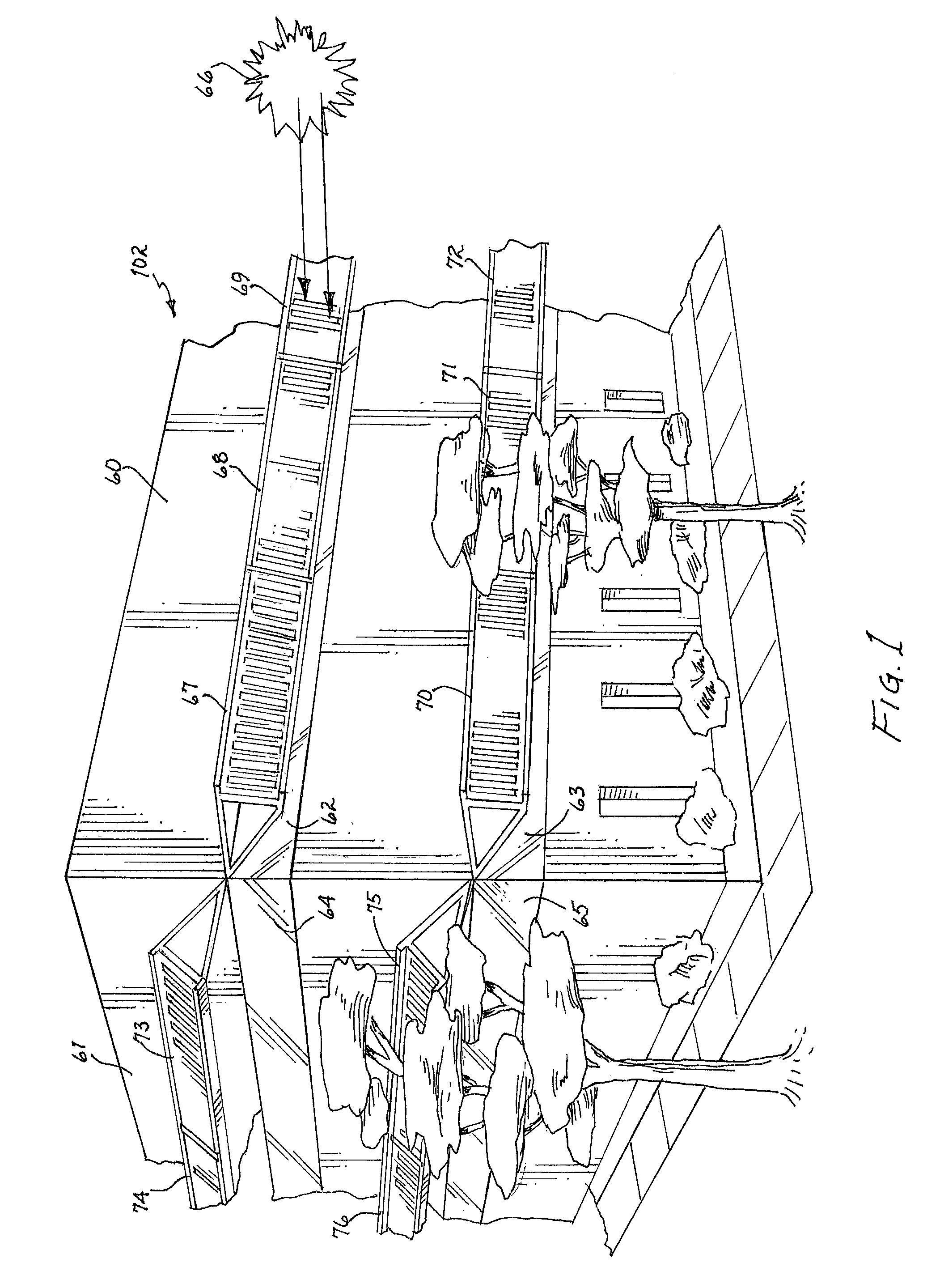
[0061]In FIG. 1, a multiple-story building 102 includes a southerly-facing wall 60 and a westerly-facing wall 61. Building 102 includes, of course, northern and eastern walls, not shown in FIG. 1. Wall 60 includes upper and lower banks of windows 62 and 63, respectively. Likewise, wall 61 includes upper and lower banks of windows 64 and 65, respectively. The sun's rays 66 are shown low in the eastern morning sky.

[0062]Installed upon the exterior of wall 60 are a series of solar window shades, constructed in accordance with the present invention. The upper bank of windows 62 is shaded by solar window shades 67, 68, and 69, while the lower bank of windows 63 is shaded by solar window shades 70, 71, and 72. All of the solar window shades 67-72 are shown pivoted downwardly to approximately the same height as their associated windows to block direct rays of incident light from the early morning sun.

[0063]Similarly, solar window shades 73 and 74 are installed proximate upper window 64 of ...


PUM


Abstract

A solar window shade includes a frame for supporting louvers for shading at least one window of a building. Preferably, the frame is pivotally connected to the building above the window, and a frame drive system selectively pivots the frame upwardly or downwardly in accordance with the elevation of the sun. A louver drive system rotates the louvers within the frame to track east-to-west movements of the sun. The louvers are preferably provided as outer and inner louvers interlaced with each other, and such louvers nest with one another when the sun is hidden, or approaches from an acute angle, to maximize passage of indirect light rays to light the interior, while minimizing obstruction of the view through the window. The device is modular and is easily applied to aligned rows of windows and / or windows on multi-story buildings, with central control of the associated frame drive and louver drive systems.

Description

BACKGROUND OF THE INVENTION[0001]1. Field of the Invention[0002]The present invention relates generally to devices for shading windows from sunlight, and more particularly, to an improved shading device which blocks direct sunlight while increasing passage of indirect light.[0003]2. Description of the Related Art[0004]Window blinds have long been available for reducing the harsh glare, and thermal heat, associated with the penetrating rays of the sun. For example, U.S. Pat. No. 169,502 to Widemann in the year 1875 discloses a venetian shade including a series of parallel slats for blocking direct rays of the sun. U.S. Pat. No. 2,749,581 issued to McCormick in 1956 discloses a form of vertical blinds wherein the louvers are disposed vertically.[0005]Awning structures have also been used on the outside of buildings adjacent windows for controlling the passage of sunlight through the window. U.S. Pat. No. 2,242,697 issued to Duca in 1940 describes an awning, including a series of horiz...

Claims


Application Information

Patent Timeline
Patent Type & Authority Patents(United States)
IPC IPC(8): E05F15/20E06B7/094E06B7/084E06B7/08
CPCE04F10/10
Inventor MURPHY, JR., JOHN A.MURPHY, III, JOHN A.
Owner MURPHY FARRELL DEV L
Why Eureka
Try Eureka