Method and system for redirecting light emitted from a light emitting diode

a technology of light emitting diodes and redirections, which is applied in outdoor lighting, semiconductor devices of light sources, lighting and heating apparatus, etc., to achieve the effect of reducing the divergence of light and facilitating the redirection of ligh

Active Publication Date: 2015-12-01
SIGNIFY HLDG BV
View PDF194 Cites 7 Cited by
  • Summary
  • Abstract
  • Description
  • Claims
  • Application Information

AI Technical Summary

Benefits of technology

[0007]An apparatus can process light emitted by one or more light emitting diodes to form a desired illumination pattern, for example successively applying at least two total internal reflections to light headed in certain directions, resulting in beneficial redirection of that light.
[0008]In one aspect of the present technology, a light emitting diode can produce light and have an associated optical axis. A body of optical material can be oriented with respect to the light emitting diode to process the produced light. The body can be either seamless or formed from multiple elements joined or bonded together, for example. A first section of the produced light can transmit through the body of optical material, for example towards an area to be illuminated. The body of optical material can redirect a second section of the produced light, for example so that light headed in a non-strategic direction is redirected towards the area to be illuminated. A refractive surface on an interior side of the body of optical material can form a beam from the second section of the produced light or otherwise reduce divergence of that light. The beam can propagate in the optical material at an angle relative to the optical axis of the light emitting diode while heading towards a first reflective surface on an exterior side of the body of optical material. Upon beam incidence, the first reflective surface can redirect the beam to a second reflective surface on an exterior side of the body of optical material. The second reflective surface can redirect the beam across the optical axis outside the body and towards the area to be illuminated. Accordingly, the first and second reflective surfaces can collaboratively redirect light from a non-strategic direction to a strategic direction. One or both of the reflective surfaces can be reflective as a result of comprising an interface between a transparent optical material having a relatively high refractive index and an optical medium having relatively low refractive index, such as a totally internally reflective interface between optical plastic and air. Alternatively, one or both of the reflective surfaces can comprise a coating that is reflective, such as a sputtered aluminum coating applied to a region of the body of optical material.
[0009]The foregoing discussion of managing light is for illustrative purposes only. Various aspects of the present technology may be more clearly understood and appreciated from a review of the following detailed description of the disclosed embodiments and by reference to the drawings and the claims that follow. Moreover, other aspects, systems, methods, features, advantages, and objects of the present technology will become apparent to one with skill in the art upon examination of the following drawings and detailed description. It is intended that all such aspects, systems, methods, features, advantages, and objects are to be included within this description, are to be within the scope of the present technology, and are to be protected by the accompanying claims.

Problems solved by technology

However, most such street lighting applications would benefit from biasing the amount of light illuminating the street relative to the amount of light illuminating the houses.

Method used


Image

  • Method and system for redirecting light emitted from a light emitting diode
  • Method and system for redirecting light emitted from a light emitting diode
  • Method and system for redirecting light emitted from a light emitting diode

Examples


Embodiment Construction

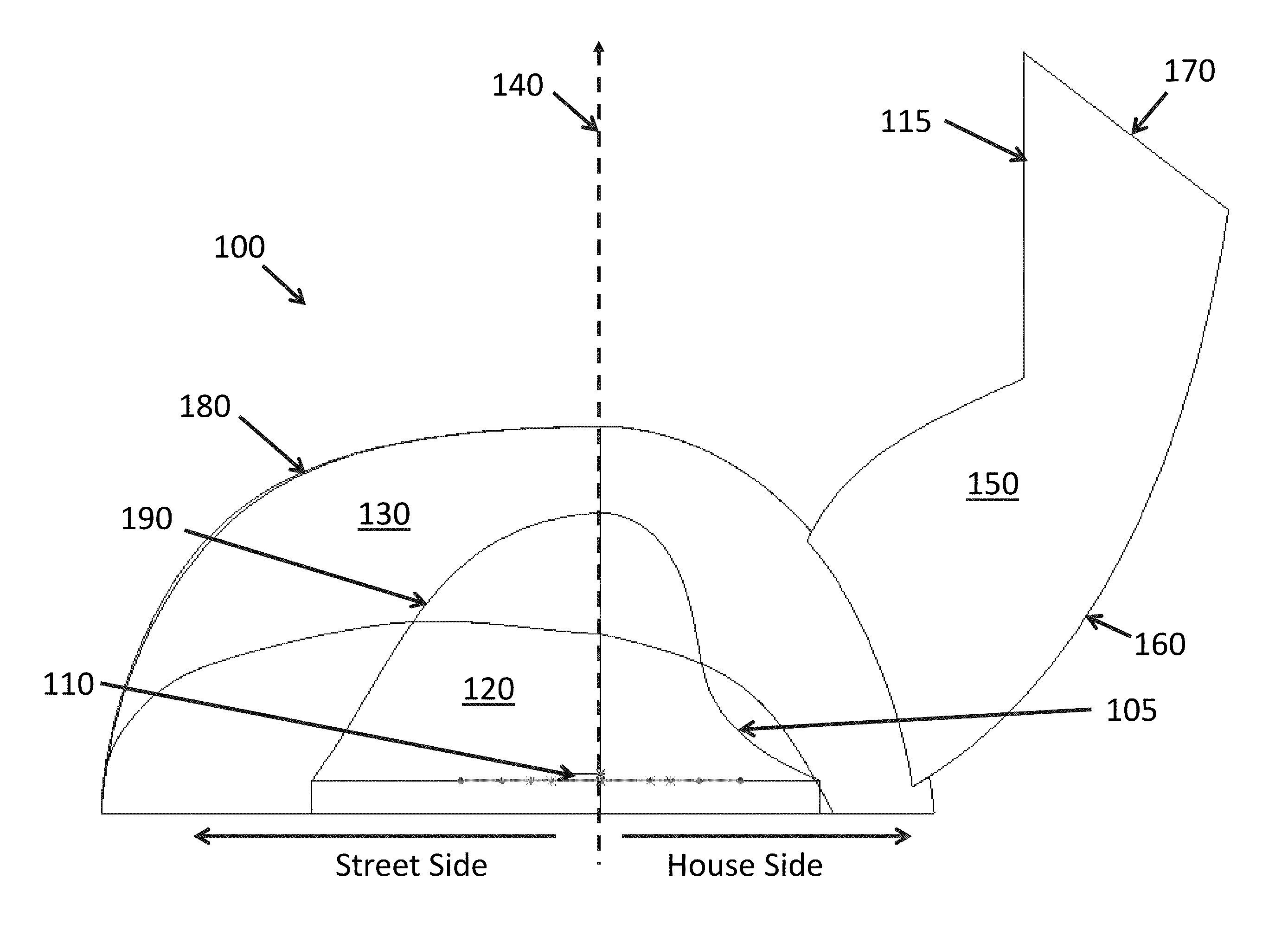
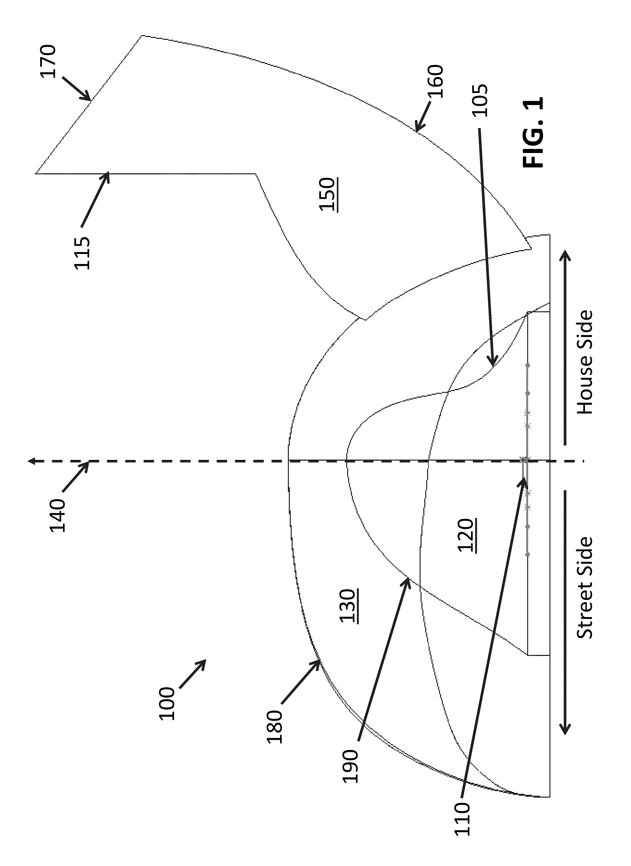
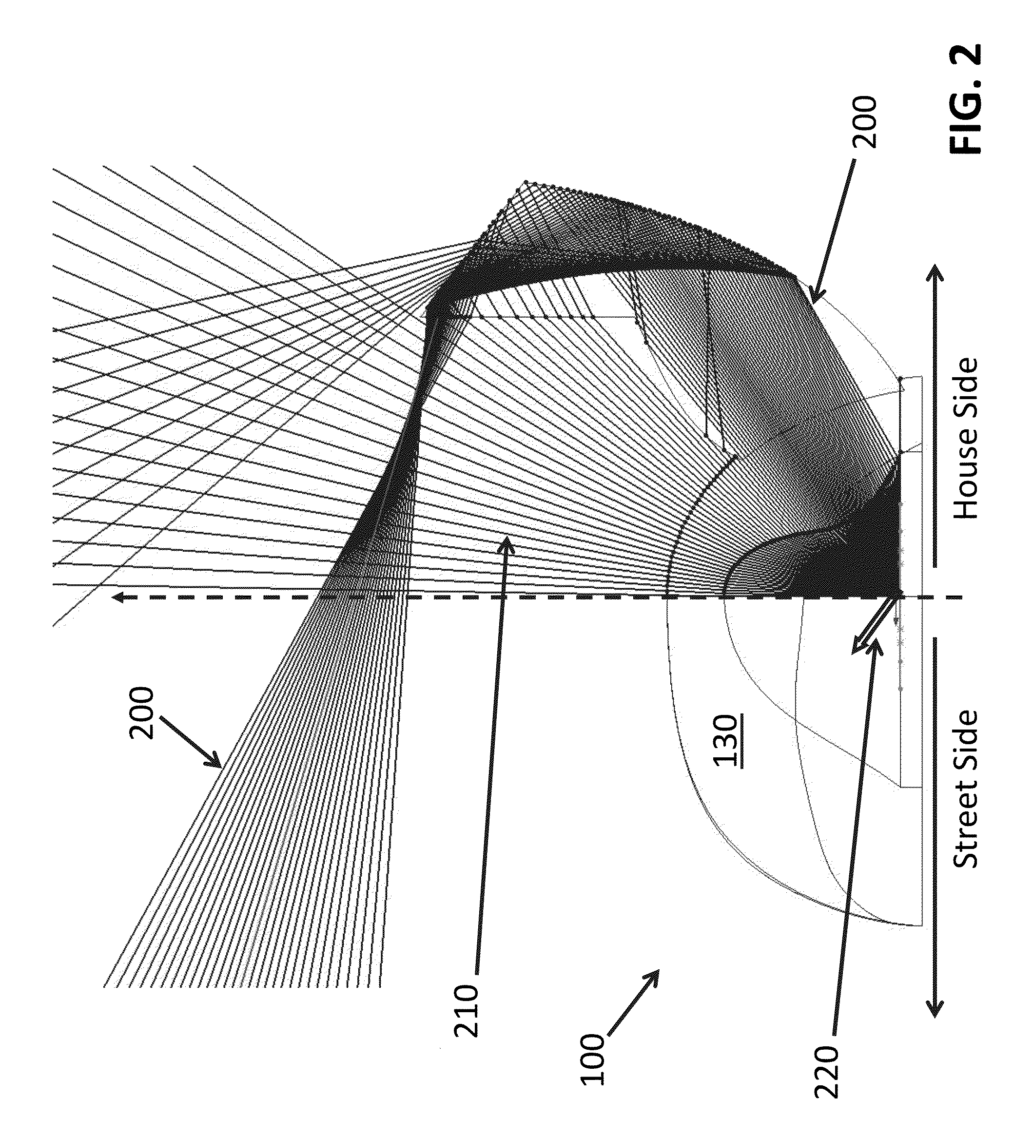
[0013]A light source can emit light. In certain embodiments, the light source can be or comprise one or more light emitting diodes, for example. The light source and / or the emitted light can have an associated optical axis. The light source can be deployed in applications where it is desirable to bias illumination laterally relative to the optical axis. For example, in a street luminaire where the optical axis is pointed down towards the ground, it may be beneficial to direct light towards the street side of the optical axis, rather than towards a row of houses that are beside the street. The light source can be coupled to an optic that receives light propagating on one side of the optical axis and redirects that light across the optical axis. For example, the optic can receive light that is headed towards the houses and redirect that light towards the street.

[0014]The optic can comprise an inner surface facing the light source and an outer surface facing away from the light source,...


PUM


Abstract

A light source, for example a light emitting diode, can emit light and have an associated optical axis. The source can be deployed in applications where it is desirable to have illumination biased laterally relative to the optical axis, such as in a street luminaire where directing light towards the street is beneficial. The source can be coupled to an optic that comprises a cavity. A first region of the optic can receive light from the source and emit light towards the area to be illuminated. A second region of the optic can comprise two reflective surfaces. The first reflective surface can receive light from the source and reflect the received light towards the second reflective surface. The two reflective surfaces can be used to direct light away from one side of the optic.

Description

RELATED APPLICATIONS[0001]The present application claims priority under 35 U.S.C. Section 119 to U.S. Provisional Application No. 61 / 728,475, filed on Nov. 20, 2012, and titled “Method and System For Redirecting Light Emitted From a Light Emitting Diode.” The foregoing application is incorporated herein in its entirety.[0002]The present application is related to U.S. Non-Provisional application Ser. No. 13 / 828,670, filed on Mar. 14, 2013, and titled “Method and System For Managing Light From a Light Emitting Diode,” which is a continuation-in-part of and claims priority to U.S. Non-Provisional application Ser. No. 13 / 407,401, filed on Feb. 28, 2012, and titled “Method and System for Managing Light from a Light Emitting Diode.” The foregoing applications are incorporated herein in their entirety.FIELD OF THE TECHNOLOGY[0003]The present technology relates to managing light emitted by one or more light emitting diodes (“LEDs”), and more specifically to optical elements that can apply s...

Claims


Application Information

Patent Timeline
Patent Type & Authority Patents(United States)
IPC IPC(8): F21V5/04F21K99/00F21V5/08F21V7/00
CPCF21K9/54F21V7/0091F21V5/08F21V5/04F21W2131/103F21Y2115/10
Inventor BROUGHTON, KEVIN CHARLES
Owner SIGNIFY HLDG BV
Why Eureka
Try Eureka