High-force robotic gripper

a robotic gripper and high-force technology, applied in the direction of manipulators, gripping heads, load-engaging elements, etc., can solve the problems of low power density of electric systems, low stiffness of gripping strength, and inability to use large-scale actuators,

Active Publication Date: 2013-09-17
HARRIS CORP
View PDF36 Cites 30 Cited by
  • Summary
  • Abstract
  • Description
  • Claims
  • Application Information

AI Technical Summary

Problems solved by technology

For example, hydraulic actuators provide a high gripping force but require high-pressure fluids and the attendant pumps and lines to supply and deliver these fluids and thus are heavy.
The same is true of pneumatic grippers, which also suffer from the defect of having a relatively low stiffness in their gripping strength.
In many applications it is not reasonable to use large, high-power actuators for the gripper due to issues relating to size, weight, power limitations or combinations thereof.
However, electric systems also suffer from low power densities.

Method used


Image

  • High-force robotic gripper
  • High-force robotic gripper
  • High-force robotic gripper

Examples


Embodiment Construction

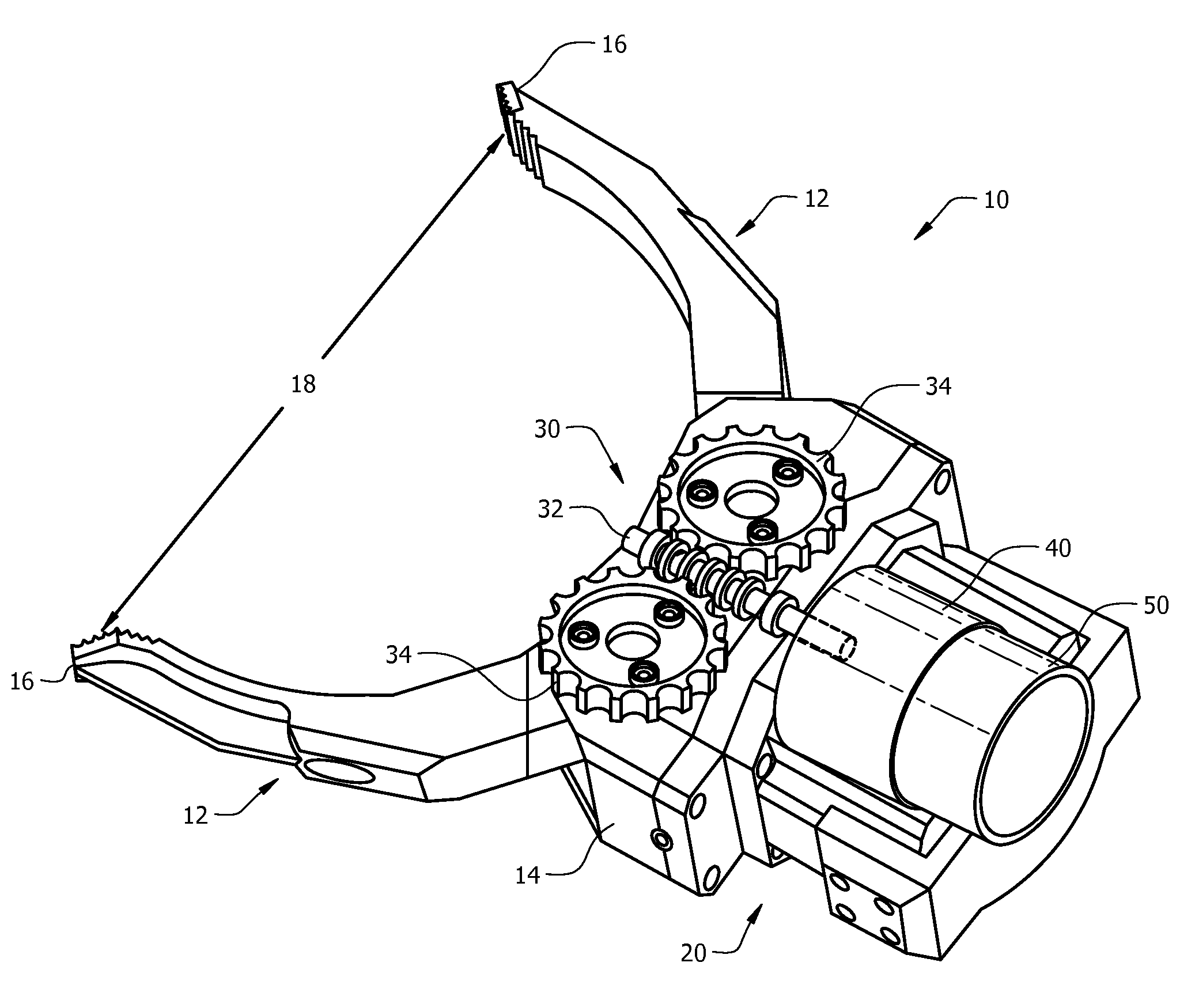
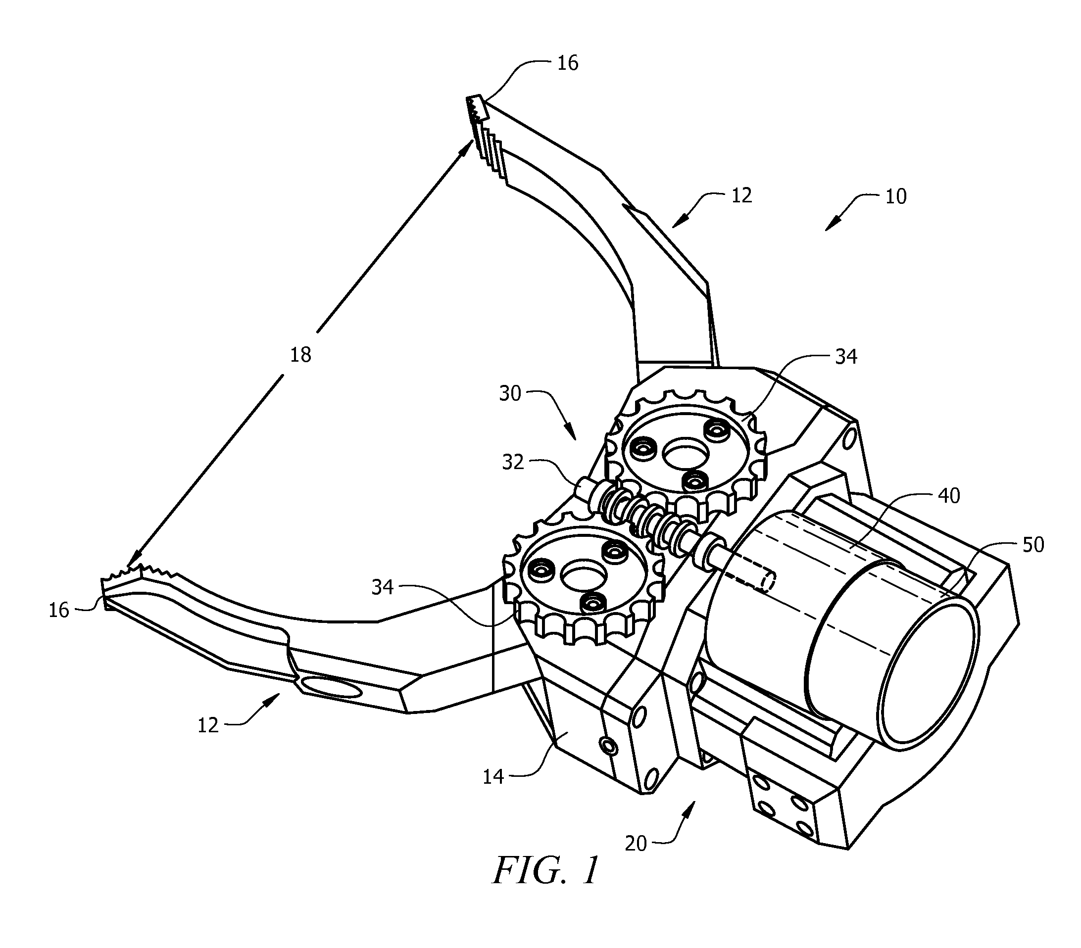
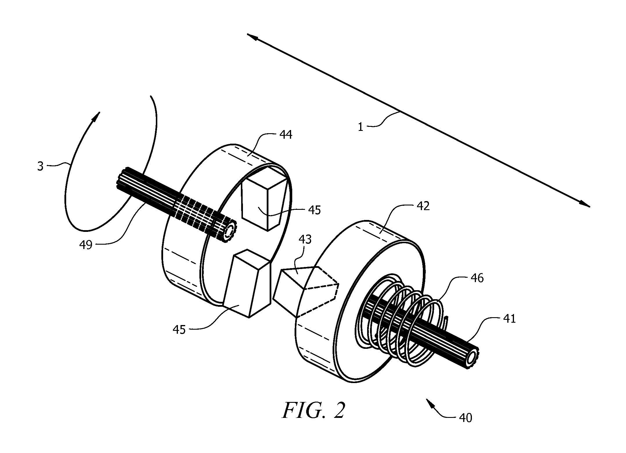
[0011]The various embodiments of the present invention are described with reference to the attached figures, wherein like reference numbers are used throughout the figures to designate similar or equivalent elements. The figures are not drawn to scale and they are provided merely to illustrate the embodiments of the present invention. Several aspects of the invention are described below with reference to example applications for illustration. It should be understood that numerous specific details, relationships, and methods are set forth to provide a full understanding of the invention. One having ordinary skill(s) in the relevant art, however, will readily recognize that the invention can be practiced without one or more of the specific details or with other methods. In other instances, well-known structures or operation are not shown in detail to avoid obscuring the invention. The present invention is not limited by the illustrated ordering of acts or events, as some acts can occu...


PUM


Abstract

A robotic gripper (10) has fingers (12) that are configured to grasp an object, and an actuator (20) for driving the fingers. The actuator has a drive train (30) connected to the fingers for driving the fingers, an impact mechanism (40) mechanically connected to the drive train for driving the drive train, and a motor (50) connected to the impact mechanism for driving the impact mechanism. The impact mechanism generates a series of impacts that are delivered to the drive train when the impact mechanism is loaded beyond a threshold torque. The drive train is a back-drive inhibited drive train provided by a worm drive (32, 34) that is mechanically coupled to the impact mechanism.

Description

STATEMENT OF THE TECHNICAL FIELD[0001]The inventive arrangements relate generally to robotic grasping devices. More particularly, the invention concerns high force robotic grippers.DESCRIPTION OF THE RELATED ART[0002]Remotely controlled robotic systems are growing increasingly common for use in areas in which a human can be subjected to dangerous or otherwise unpleasant work environments. One important component of a robotic system is a grasping device or gripper used to grasp objects that are to be lifted, moved or otherwise manipulated. Typical grippers include one or more robot fingers that can be moved by an actuator to effect such grasping operations.[0003]For many tasks it is desirable that the gripper have both a high closing speed and a high gripping force. For example, grippers for small mobile robots might need to be able to grip a 6-inch diameter object with 40 lbs of gripping force and fully close in one second. To achieve both of these goals a high-power actuator is gen...

Claims


Application Information

Patent Timeline
Patent Type & Authority Patents(United States)
IPC IPC(8): B25J15/02B25J15/08
CPCB25J15/08B25J15/024
Inventor WILKINSON, LORAN J.SUMMER, MATTHEW D.RUST, JOHN B.BOSSCHER, PAUL M.
Owner HARRIS CORP
Why Eureka
Try Eureka