Rear aerodynamic device for a vehicle and vehicle equipped with such a device

a technology for aerodynamic devices and vehicles, which is applied in the direction of roofs, vehicle arrangements, transportation and packaging, etc., can solve the problems of high drag coefficient of vehicles, high wake, and inability to maintain the vehicle, so as to improve the aerodynamics of vehicles, reduce wake, and facilitate the assembly of vehicles

Active Publication Date: 2013-09-24
VOLVO LASTVAGNAR AB
View PDF11 Cites 16 Cited by
  • Summary
  • Abstract
  • Description
  • Claims
  • Application Information

AI Technical Summary

Benefits of technology

[0007]It is also desirable to provide a vehicle with a lower aerodynamic drag.
[0029]It can be envisaged that the vehicle comprise at least one side wing extending from a vertical rear edge of the cargo body, said wing extending downwards substantially as far as the nozzle lower wall, in the prolongation of the nozzle outer wall. This improves the air guiding by preventing the air flow to deviate outwardly downstream the nozzle outlet.

Problems solved by technology

The air drag of a vehicle and especially of an industrial vehicle such as a truck is one of the factors that has a direct impact on fuel consumption.
Therefore, in a general trend towards rare and expensive energy—whether fossil or not—, aerodynamics is one of the key issue in an efficient vehicle.
One problem with the current industrial vehicles is that air passing longitudinally rearward along the side walls of the vehicle tends to deviate outward behind the vehicle rear wall.
This makes the drag coefficient of the vehicle high, which, consequently, generates a high fuel consumption.
However, these devices don't make it possible to efficiently canalize air, and they may create turbulence in other locations.
Moreover, many of these known devices cannot be properly integrated into the general structure of the vehicle.
One of the specific problems of industrial vehicles is their substantially parallelepiped shape.
To maximise the vehicle cargo it is not possible to depart from an angular shape which is however not desirable in terms of aerodynamics.

Method used


Image

  • Rear aerodynamic device for a vehicle and vehicle equipped with such a device
  • Rear aerodynamic device for a vehicle and vehicle equipped with such a device
  • Rear aerodynamic device for a vehicle and vehicle equipped with such a device

Examples


Embodiment Construction

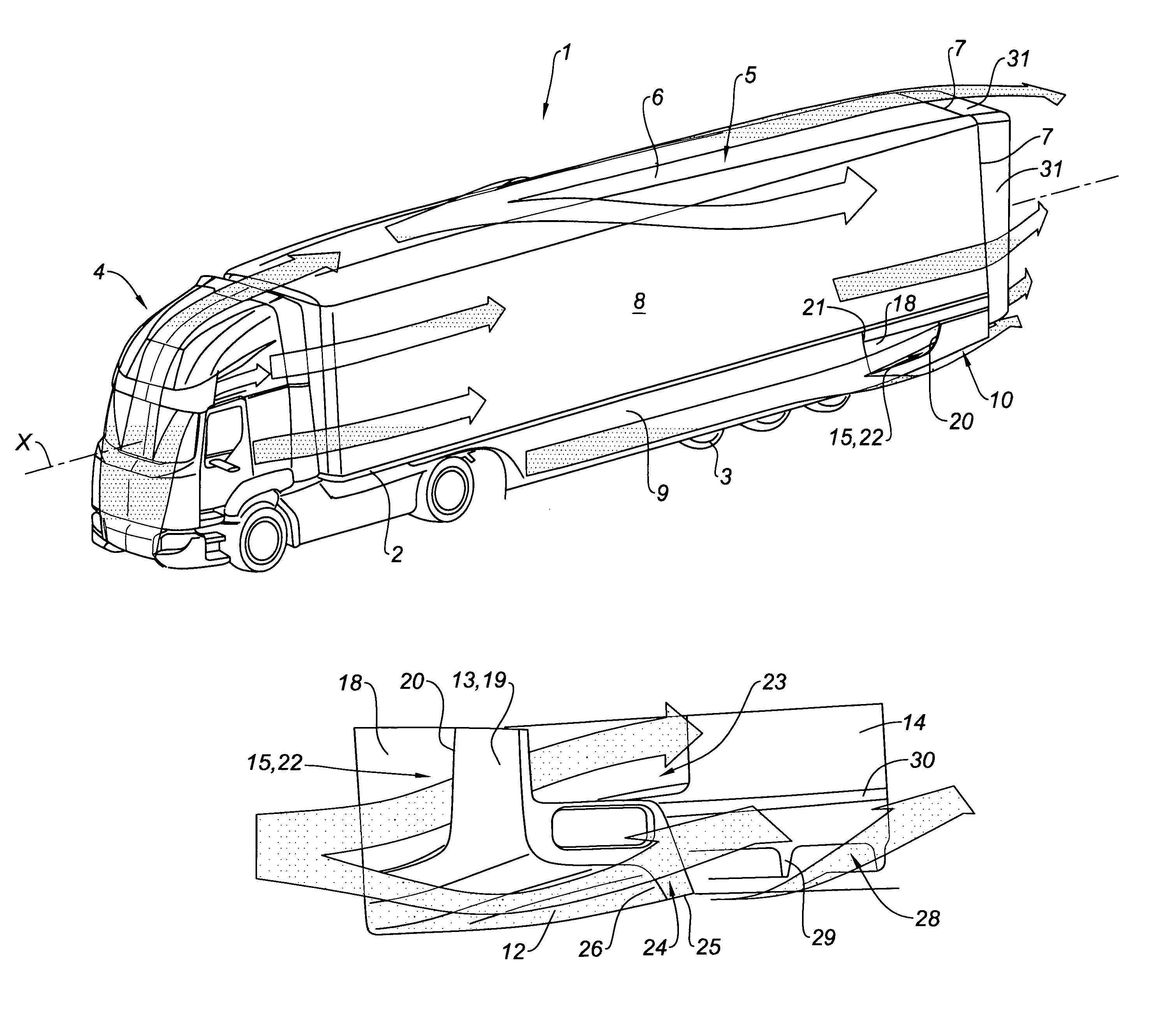
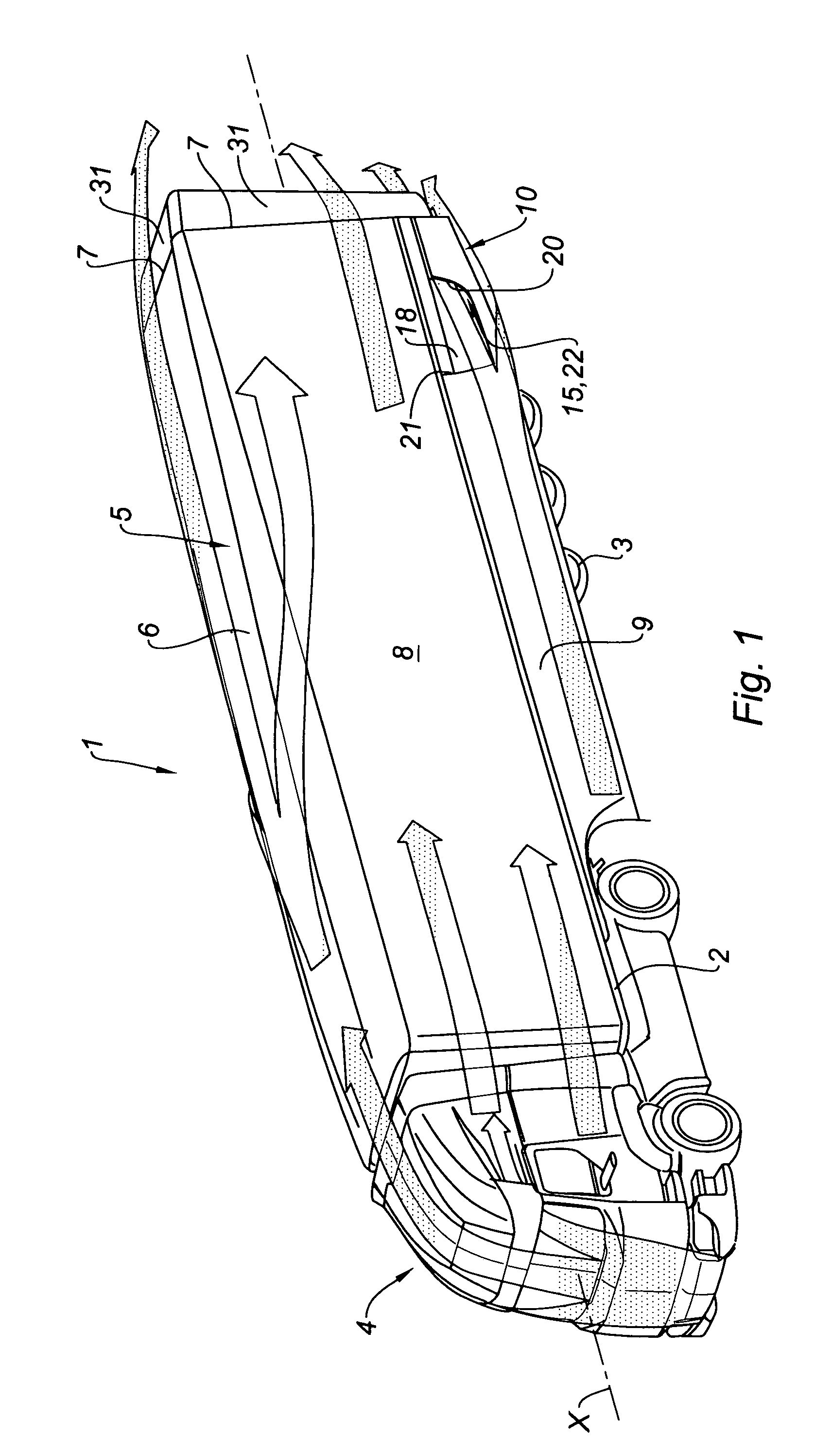
[0037]As this is illustrated in FIG. 1, a vehicle 1 comprises a frame 2 supported by wheels 3 as well as a cab 4 and a cargo body 5 supported on the frame 2. In this embodiment, the vehicle is a semi-trailer, but the invention also concerns trailers or straight trucks (i.e. a vehicle with the cargo body and the tractor mounted on the same frame).

[0038]The cargo body 5 has an upper wall 6, rear edges 7 substantially forming a rectangle, and two side walls 8. The cargo body 5 also comprises, on each side, a side panel 9 fastened to the frame 2, along and outside the wheels 3.

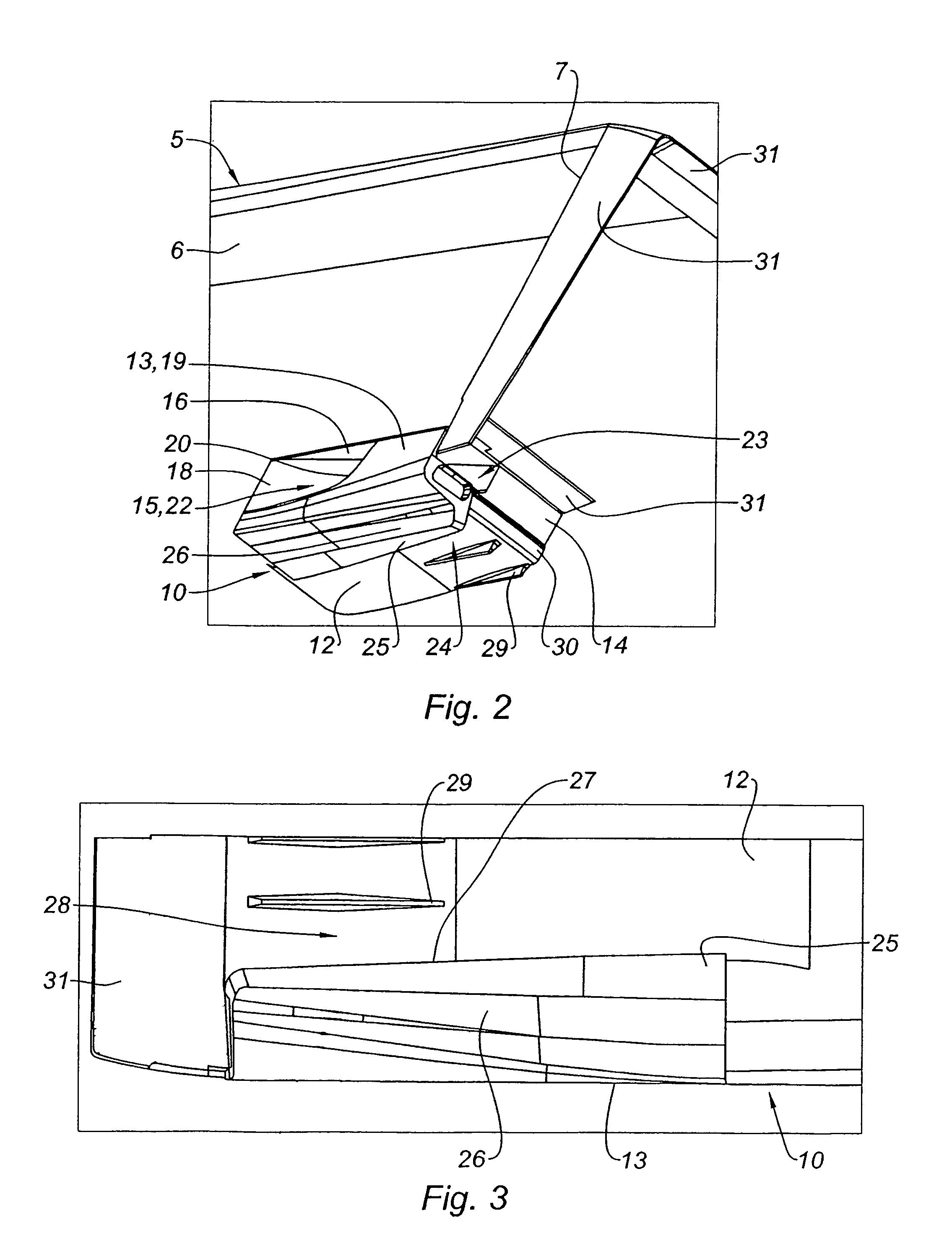
[0039]The vehicle 1 comprises an aerodynamic device 10 which is roughly shaped as a parallelepiped block and is fastened under the vehicle frame 2, close to the rear edge of the cargo body 5, behind the wheels 3. Said device 10 has substantially the same width as the cargo body 5, and therefore extends from one side wall 8 to the other. The device 10 has a vertical longitudinal plane of symmetry P, as vehicle 1 (s...


PUM


Abstract

A rear aerodynamic device for a vehicle and vehicle equipped with such a device are provided. The aerodynamic device can be fastened under a rear end of a vehicle frame of a cargo body of an industrial vehicle, behind the wheels. It includes a nozzle having an inlet positioned on a lateral external face of the device and capable of canalising air flowing along the vehicle and an outlet positioned at the rear part of the device and capable of ejecting the air flow underneath a vehicle rear face.

Description

BACKGROUND AND SUMMARY[0001]The present invention relates to an automotive vehicle, especially an industrial vehicle. More specifically, the invention concerns a rear aerodynamic device for a vehicle and a vehicle equipped with such a device.[0002]For many years, attempts have been made to improve vehicle efficiency. One factor in an efficient design is the aerodynamic characteristics of a vehicle. The air drag of a vehicle and especially of an industrial vehicle such as a truck is one of the factors that has a direct impact on fuel consumption. Therefore, in a general trend towards rare and expensive energy—whether fossil or not—, aerodynamics is one of the key issue in an efficient vehicle.[0003]One problem with the current industrial vehicles is that air passing longitudinally rearward along the side walls of the vehicle tends to deviate outward behind the vehicle rear wall. Such an air path is riot favourable because it causes turbulence and, moreover, contributes to the creatio...

Claims


Application Information

Patent Timeline
Patent Type & Authority Patents(United States)
IPC IPC(8): B62D35/00
CPCB62D35/001B62D35/02Y02T10/88Y02T10/82
Inventor KINT, LAURENT
Owner VOLVO LASTVAGNAR AB
Why Eureka
Try Eureka