Wear and shock resistant escapement lever for a timepiece movement

a technology of escapement mechanism and timepiece movement, which is applied in the field of escapement mechanism and timepiece mechanism, can solve the problems of deterioration of movement properties, drop in amplitude, decrease in overall efficiency of escapement, etc., and achieve the effect of softening the shock

Active Publication Date: 2013-09-24
ETA SA MFG HORLOGERE SUISSE
View PDF20 Cites 9 Cited by
  • Summary
  • Abstract
  • Description
  • Claims
  • Application Information

AI Technical Summary

Benefits of technology

[0015]The invention therefore concerns a escapement lever for the escapement mechanism of a timepiece movement, including at least one fork delimiting a notch, which includes horns arranged for cooperating with a balance, characterized in that said fork notch includes, in at least one of said horns, a slot and / or a chamber, for delimiting at least one elastic lip extending between a contact surface and said slot or chamber, said slot or chamber being arranged to confer some elasticity on the corresponding horn, which softens the shock during each impulse by absorbing part of the impact energy and then returning it subsequent to said impact.

Problems solved by technology

These incessant shocks generate wear, and thus over time cause deterioration of the properties of the movement.
In particular, in an escapement mechanism, wear at the fork notches results in a decrease in the overall efficiency of the escapement and a drop in amplitude.
The problem is therefore to reduce the wear of the escapement mechanism, particularly the escapement lever, and to make the contact zone between the escapement lever and the balance elastic, while respecting the space requirements imposed by the mechanism.
The choice of particular materials or surface coatings does not reduce shocks, but delays the effect thereof.
The use of ball bearings is ill-suited to a system permanently subject to shocks, and the lifetime of bearings in such mechanisms is generally reduced, which is incompatible with a timepiece.
Reducing inertia is more advantageous, but it is difficult to act on an existing movement and modify its kinematics.
This arrangement is not applicable to numerous components, for which pivoting mobility is incompatible with their operational kinematics.
Although this type of wheel may suit an escapement wheel, like the preceding patent document, the arrangement thereof is less suitable for the particular kinematics linked to certain components such as escapement levers.

Method used


Image

  • Wear and shock resistant escapement lever for a timepiece movement
  • Wear and shock resistant escapement lever for a timepiece movement
  • Wear and shock resistant escapement lever for a timepiece movement

Examples


fourth embodiment

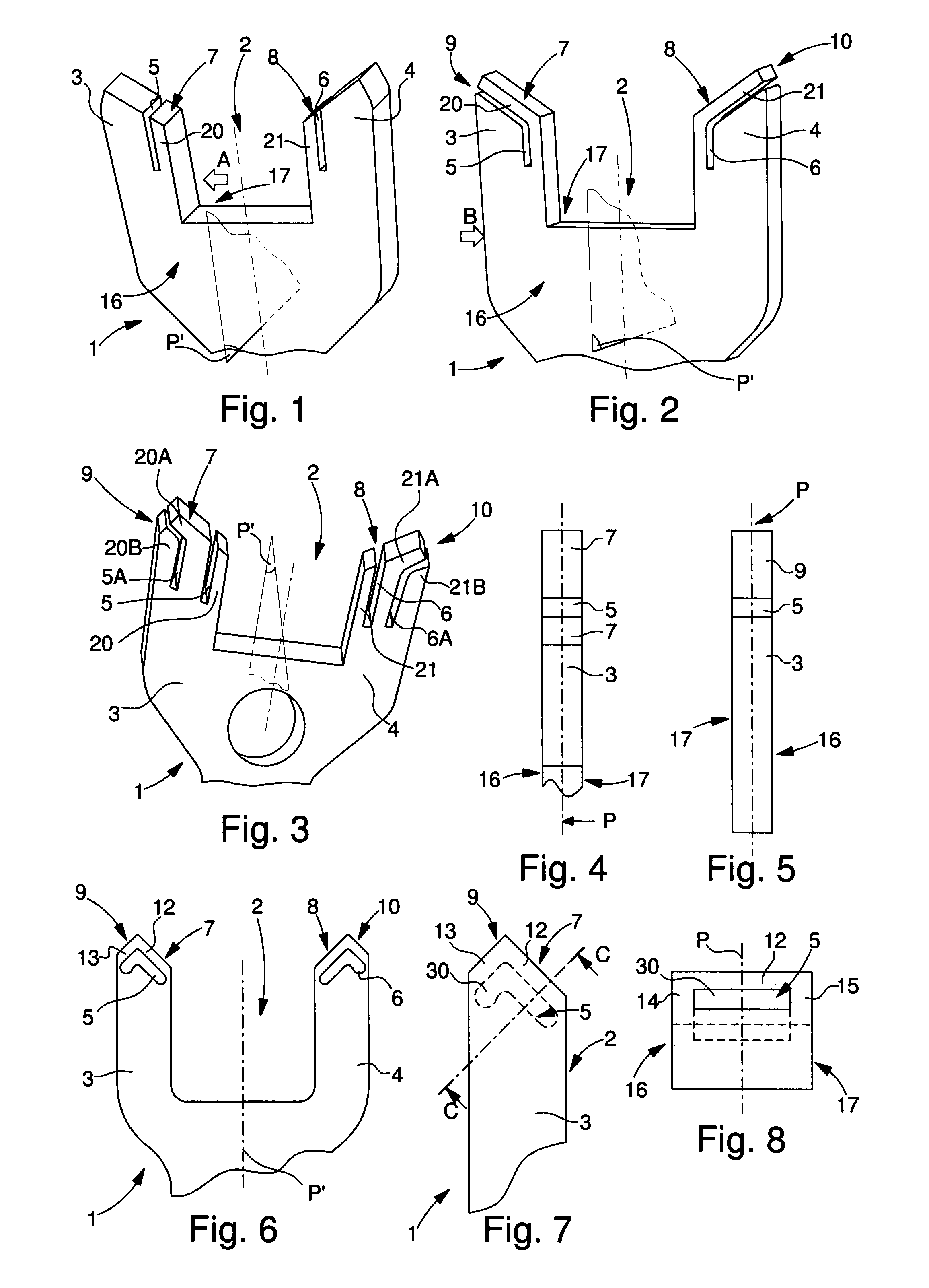
[0084]A fourth embodiment is shown in FIG. 6 in which the elastic slot 5, 6 does not open at an inner end surface 7, 8 or outer end surface 9, 10, but only at least one of lateral faces 16, 17 comprised in escapement lever 1, parallel to the plane P thereof. Preferably, for the symmetry of the internal stresses, the slot opens at the two opposite lateral faces.

[0085]A fifth variant is shown in FIGS. 7 and 8. It includes at least one chamber 30 inside one horn. This chamber 30 does not have an opening, and it is housed entirely within the thickness of the horn 3, 4, with no access to any of the external surfaces thereof. This chamber 30 is preferably delimited, on the side of inner end surface 7 and external end surface 9, by external areas which are elastic lips of small section 12, 13, such that the end of the horn has elastic behaviour. Preferably and for the same purpose, chamber 30 is also delimited by a lateral area of small section 14, 15, on the side of each of the lateral su...

fifth embodiment

[0101]Thus, it is possible and particularly easy to make escapement lever 1, in particular in a micromachinable material using MEMS technology or the LIGA process or suchlike. Preferably, escapement lever 1 is made in a micro-machinable material using the LIGA method.

[0102]Thus, the choice of this micro-machinable material allows very fine slots or chambers to be made accurately, with no concerns as to the existence of a local defect in material, a pre-fissure, or even local internal over-stresses, which are more frequently encountered with a more conventional steel or alloy. The very small size of the smallest dimensions of the slot or chamber limits the vibration amplitude of the elastic lips, prevents any non-reversible deformation and avoids any breakage of the lips.

[0103]It is naturally possible to make a component with elastic lips according to the invention in another material, steel or alloy, advantageously with a layer deposited on the surface of said component, or even us...


PUM


Abstract

The invention concerns a escapement lever (1) for the escapement mechanism of a timepiece movement, including at least one fork delimiting a notch (2) which includes horns (3; 4) arranged for cooperating with a balance.Said fork notch (2) includes, in at least one said horn (3; 4), a slot (5, 6) and / or a chamber (30), wherein said slot (5; 6) and / or chamber (30) is arranged to confer elasticity on the corresponding horn, which softens the shock at each impulse, by absorbing part of the impact energy, and then returning it subsequent to said impact.

Description

[0001]This application claims priority from European Patent Application No. 10171477.2 filed Jul. 30, 2010, the entire disclosure of which is incorporated herein by reference.FIELD OF THE INVENTION[0002]The invention concerns an escapement lever for the escapement mechanism of a timepiece movement, including at least one fork delimiting a notch which includes horns arranged for cooperating with a balance.[0003]The invention also concerns an escapement mechanism including an escapement lever of this type.[0004]The invention also concerns a timepiece including at least one escapement lever of this type, and / or escapement mechanism of this type.BACKGROUND OF THE INVENTION[0005]The invention concerns the field of timepiece mechanisms, and more specifically the field of escapement mechanisms.[0006]In a mechanism of this type, the escapement lever cooperates both with a balance and with an escapement wheel. On both sides, the escapement lever works with shocks, on the one hand via the for...

Claims


Application Information

Patent Timeline
Patent Type & Authority Patents(United States)
IPC IPC(8): G04B15/00
CPCG04B15/14G04B43/002
Inventor RICHARD, DAVIDCABEZAS JURIN, ANDRES
Owner ETA SA MFG HORLOGERE SUISSE
Why Eureka
Try Eureka