Excavator, mounting device and excavator tool

a technology for mounting devices and excavators, which is applied in the direction of mechanical machines/dredgers, soil shifting machines/dredgers, constructions, etc., can solve problems such as fatigue damage of excavator structures, and achieve the effect of eliminating the risk of edge cuts

Inactive Publication Date: 2013-10-15
ATLAS COPCO ROCK DRILLS
View PDF13 Cites 0 Cited by
  • Summary
  • Abstract
  • Description
  • Claims
  • Application Information

AI Technical Summary

Benefits of technology

[0008]This object is achieved by an excavator that comprises a drive unit, a removable or non-removable excavator tool, and a mounting device that comprises at least two arms that are arranged to be connected to the excavator tool. The excavator comprises resilient means that are located in at least two different locations. The resilient means are arranged to allow the excavator tool to move in at least one plane relative to the drive unit when said excavator tool is mounted on the mounting device and thereby allows the excavator tool to oscillate in said at least one plane. Since the resilient means are arranged in at least two different locations, for example on each side of the mounting device, one side of the excavator tool can move without substantially influencing the other side of the excavator tool.
[0011]Such a construction provides an excavator with a robust mounting device that facilitates oscillation of an excavator tool, i.e. it facilitates the excavator tool's swinging from side to side, and / or up and down and / or in some other plane. Both the oscillation resistance and the oscillation movement's size can be varied by varying the type, the rigidity and / or the dimensions of the resilient means and / or their placement. The excavator according to the present invention is resistant to fatigue since the oscillation is taken up by the resilient means, via springs for example, and not by twisting the mounting device itself or some other part of the excavator. Furthermore the force that is used to oscillate the excavator tool is independent of the compressive force. Such an excavator therefore makes it possible to oscillate the excavator tool in an effective and simple way.
[0018]According to an embodiment of the invention the at least two arms are mounted in spherical bearing in the mounting device. Since all of the arms joints have spherical joint bearings instead of bushings the risk of edge cuts is eliminated.
[0019]According to another embodiment of the invention the mounting device comprises locking means in order to prevent the excavator tool from being able to move in at least one plane relative to the drive unit. For example, if the excavator is to be used for excavating a substantially horizontal surface, the excavator tool can be prevented from being able to move in the excavator's transverse direction.

Problems solved by technology

The expression excludes the unavoidable play between fixedly mounted components of an excavator, which play can result in fatigue damage of the excavator structure.

Method used


Image

  • Excavator, mounting device and excavator tool
  • Excavator, mounting device and excavator tool
  • Excavator, mounting device and excavator tool

Examples


Embodiment Construction

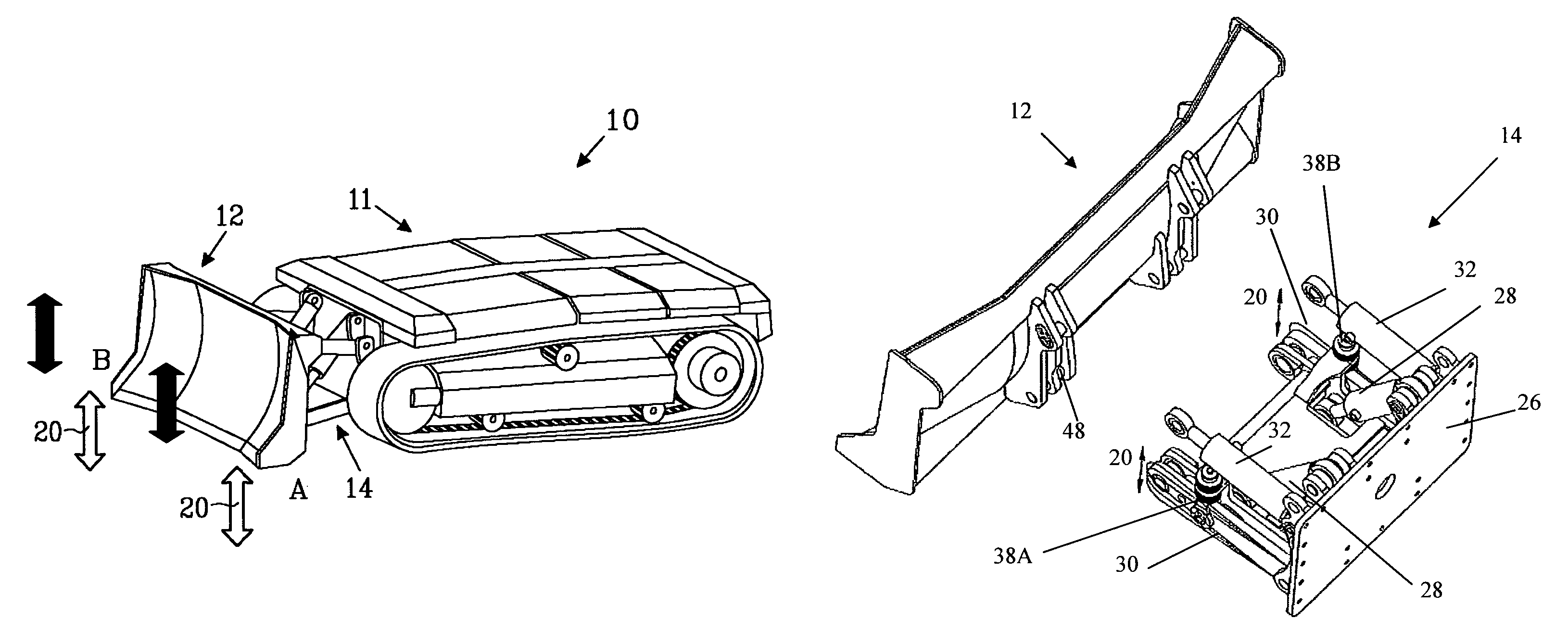
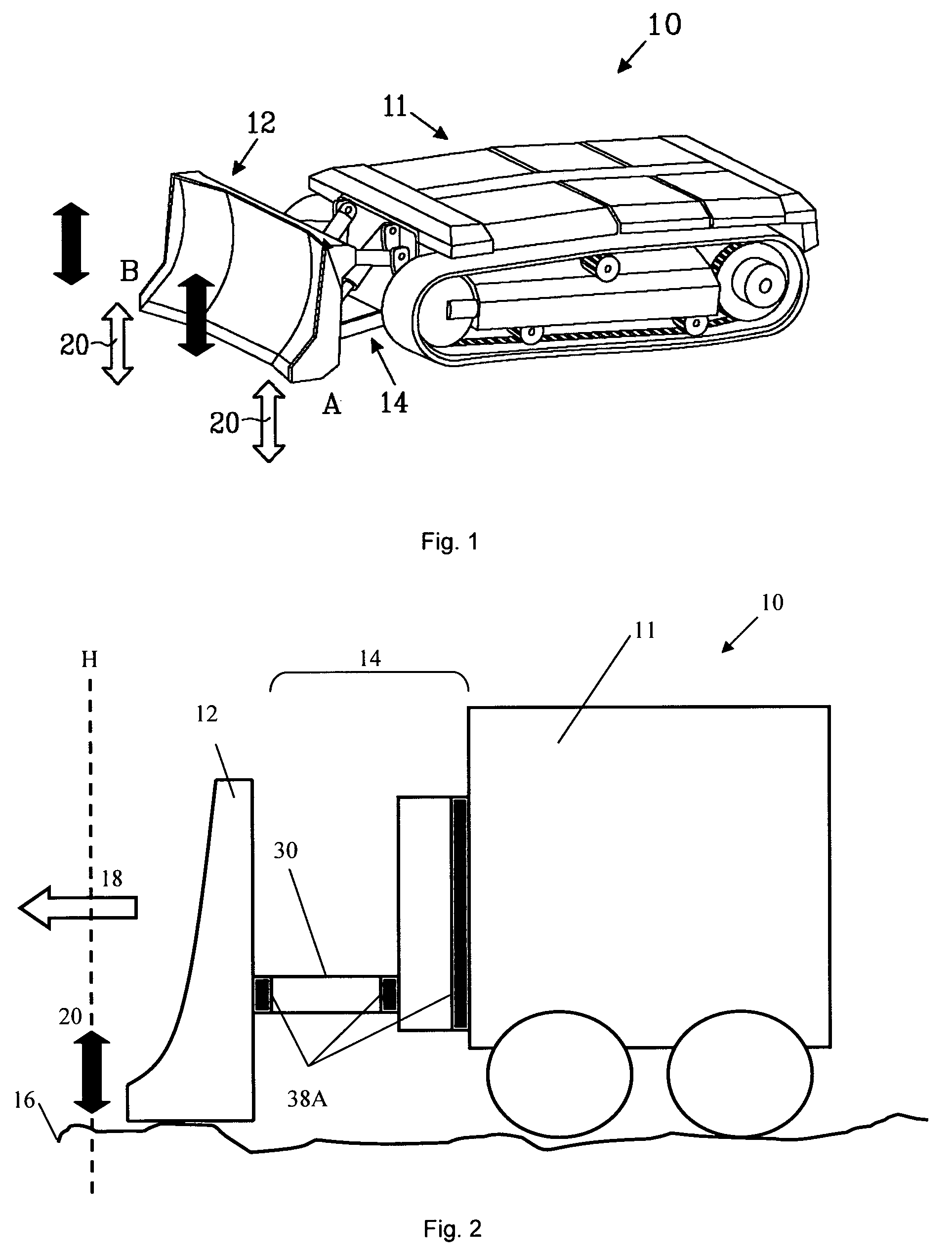
[0031]FIG. 1 shows an excavator 10, such as a belt excavator, that comprises a drive unit 11, an excavator tool 12, namely an excavator blade in the illustrated example, and a blade mounting device 14. Each side A, B, of the excavator blade 12 is arranged to move up and down in a substantially vertical plane as is indicated by the block arrows 20, i.e. the excavator tool 12 is arranged to oscillate from side to side in the substantially vertical plane.

[0032]FIG. 2 schematically shows an excavator 10, whose drive unit 11 moves an excavator blade 12 over a hard and rough underlying surface 16 in the direction shown by the block arrow 18. The excavator blade 12 is arranged to oscillate in the substantially vertical plane 20 and follow the underlying surface contours 16, whereby the excavator blade 12 becomes easier to move forwards. At the same time the underlying surface 16 becomes more scraped clean and the forces to which the blade mounting 14 is subjected lower. The mounting device...


PUM


Abstract

Excavator that comprises a drive unit, an excavator tool and a mounting device for the excavator tool and wherein the mounting device comprises at least two arms that are arranged to be connected to the excavator tool. The excavator comprises resilient portions located in at least two different locations in which the resilient portions are arranged to allow the excavator tool to move in at least one plane relative to the drive unit when the excavator tool is mounted on the mounting device and thereby allow the excavator tool to oscillate in the at least one plane.

Description

[0001]This application is a U.S. National Phase Application under 35 USC 371 of International Application PCT / SE2009 / 050201, filed Apr. 29, 2008.TECHNICAL FIELD[0002]The present invention concerns an excavator and a mounting device as well as an excavator tool for such an excavator.BACKGROUND OF THE INVENTION[0003]An excavator is a type of engineering machine that is mainly used for moving earth or loads, digging work and demolition. An excavator, such as a digging machine, usually comprises a drive unit that comprises an undercarriage and an overcarriage, whereby the overcarriage has a motor and cabin part that can be rotated in relation to the undercarriage. Excavators also comprise an assembly that includes an excavator tool, such as a blade, a shovel, a hook for breaking up frozen ground, an asphalt cutter or a gripping tool, that is attached to the excavator's underbody via a mounting device, and that is usually hydraulically controlled using at least a hydraulically maneuvered...

Claims


Application Information

Patent Timeline
Patent Type & Authority Patents(United States)
IPC IPC(8): E02F3/76
CPCE02F3/38E02F3/7613E02F3/7618
Inventor MARTINSSON, CARL-GUSTAVGUSTAFSSON, SVEN-AKEJONSSON, ULFKRISTERSON, MATSNILSSON, JESPER
Owner ATLAS COPCO ROCK DRILLS
Why Eureka
Try Eureka