
Method of deploying a bifurcated side-access intravascular stent graft

a stent and side access technology, applied in the field of intravascular stent grafts, can solve the problems of inadequacies of prior art devices, significant morbidity or even sudden death, and progression of damage to the affected area

Inactive Publication Date: 2013-10-15
WL GORE & ASSOC INC
View PDF25 Cites 24 Cited by
  • Summary
  • Abstract
  • Description
  • Claims
  • Application Information

AI Technical Summary

Benefits of technology

Enables accurate and safe deployment of stent grafts in vessels with large-angle branch vessels, providing a fluid-tight seal and maintaining blood flow, addressing the limitations of previous devices by allowing transluminal deployment without distal access through the branch vessel.

Problems solved by technology

Continued exposure to such fluid pressure may result in progression of damage to the affected area and / or vessel failure, accompanied by significant morbidity or even sudden death.
Complications arise, however, when vessel damage occurs near a vessel branch point.
For larger branching angles (as large as about 90° or even up to about 180°, for example) many prior art devices are not suitable.
Another drawback common to many devices of the prior-art is the need for transluminal access through the branch vessel from a point distal of the repair site.
In many instances such access is either impossible (celiac artery, mesenteric arteries, renal arteries) or extremely difficult and / or dangerous (carotid arteries).
Still other previous devices do not provide a substantially fluid-tight seal with the branch vessel, thereby partially defeating the purpose of the stent graft (i.e., shielding the repaired portion of the main vessel and / or branch vessel from intravascular fluid pressure).

Method used


Image

  • Method of deploying a bifurcated side-access intravascular stent graft
  • Method of deploying a bifurcated side-access intravascular stent graft
  • Method of deploying a bifurcated side-access intravascular stent graft

Examples


Embodiment Construction

[0065]For purposes of the present written description and / or claims, “proximal” shall denote the direction along a vessel system in which multiple smaller vessels come together to form a larger vessel, and “distal” shall denote the opposite direction, i.e., the direction in which a larger vessel divides into multiple smaller vessels. For an arterial system proximal therefore corresponds to “upstream”, while distal corresponds to “downstream”. It should be noted that for a venous system or a lymphatic system, the correspondence would be reversed. The correspondence may vary for other vascular or duct systems.

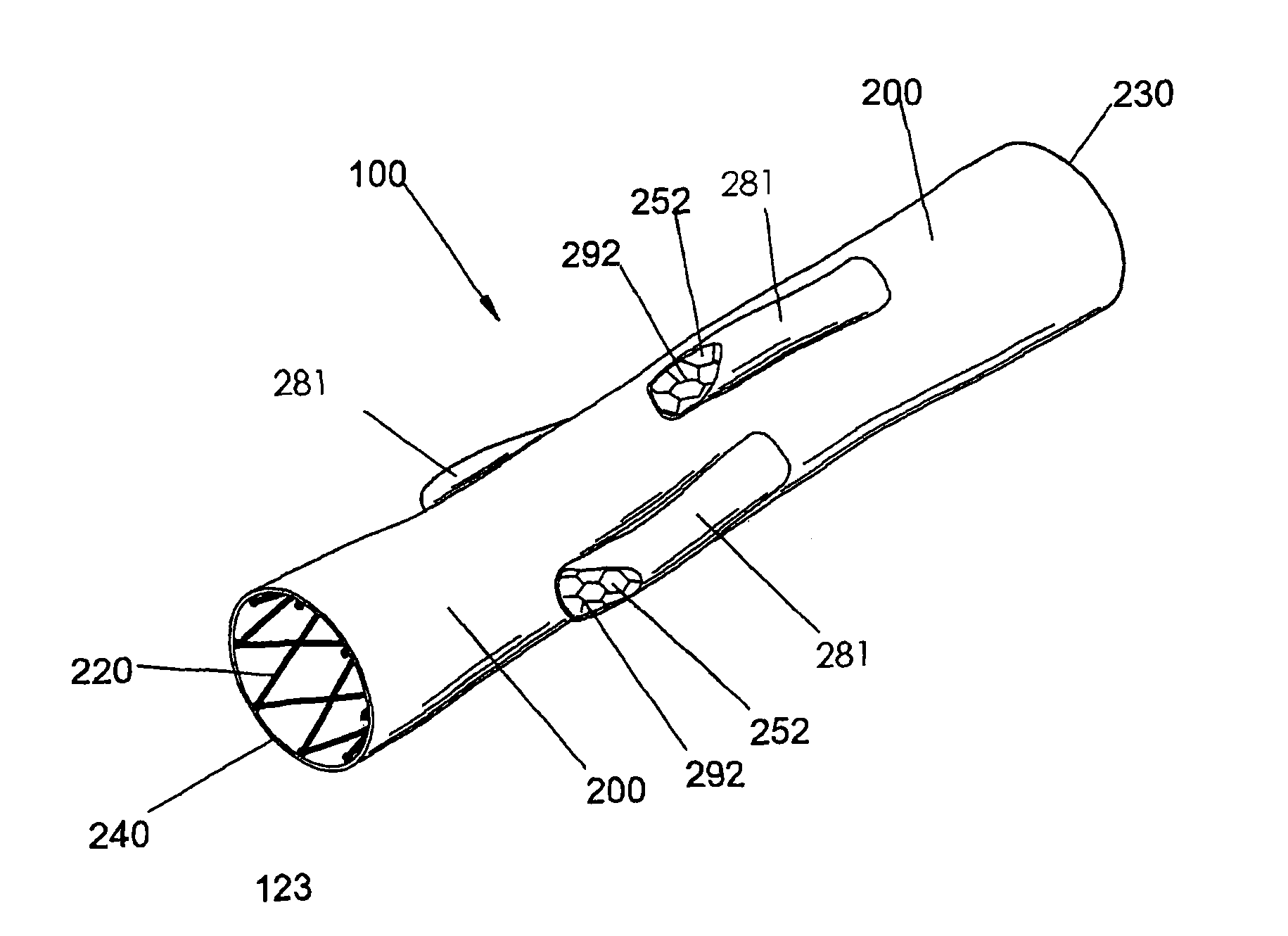
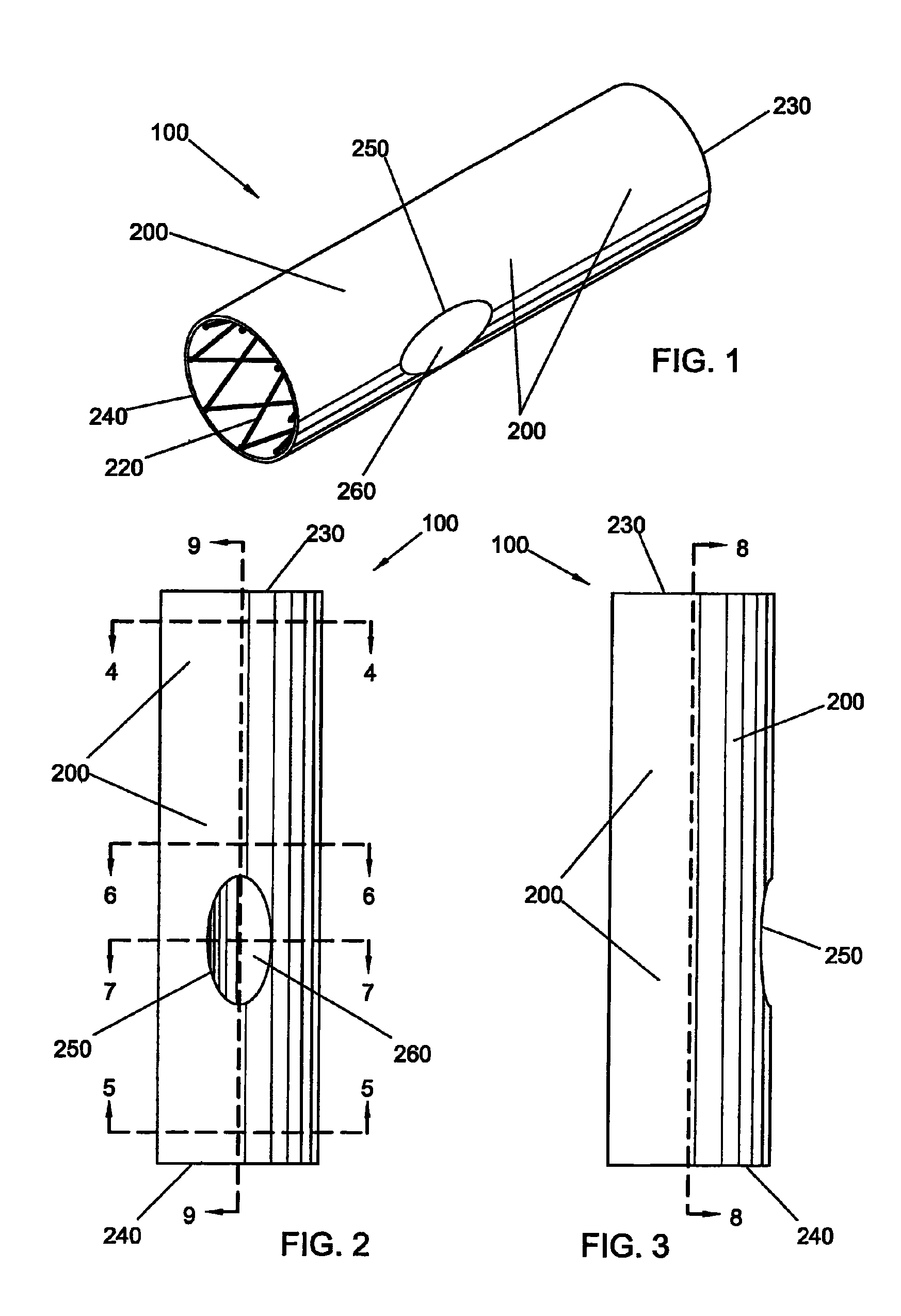
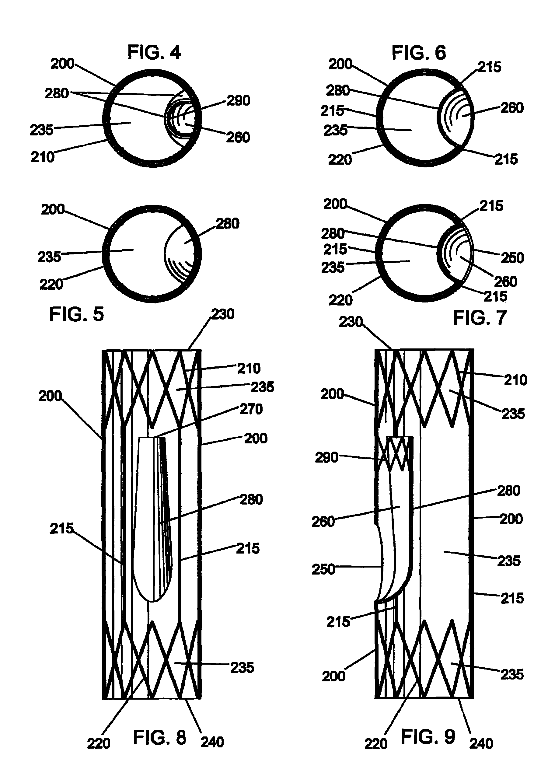
[0066]A bifurcated intravascular primary stent graft 100 according to the present invention is illustrated in FIGS. 1-9 and comprises: a first primary stent segment 210; a second primary stent segment 220; a primary graft sleeve 200 having first open end 230, having a second open end 240, forming a main fluid flow channel 235 therebetween, and having a side opening 250 therethrou...


PUM


Abstract

A bifurcated intravascular stent graft comprises primary stent segments and a primary graft sleeve, forming a main fluid channel and having a side opening therethrough. An external graft channel formed on the primary graft sleeve has a first end communicating with the side opening and an open second end outside the primary graft sleeve, thereby providing a branch flow channel from the main channel out through the side opening and external graft channel. The primary stent segments and graft sleeve engage an endoluminal surface of a main vessel and form substantially fluid-tight seals. The stent graft further comprises a secondary stent graft, which may be positioned partially within the external graft channel, through the open second end thereof, and partially within a branch vessel. The secondary stent graft engages the inner surface of the external graft channel and the endoluminal surface of the branch vessel, thereby forming substantially fluid-tight seals.

Description

CROSS-REFERENCE TO RELATED APPLICATIONS[0001]This application is a division of U.S. application Ser. No. 10 / 277,641 filed Oct. 22, 2002 now abandoned, which is a continuation-in-part of U.S. application Ser. No. 09 / 734,987 filed Dec. 11, 2000, now issued U.S. Pat. No. 6,645,242.FIELD OF THE INVENTION[0002]The field of the present invention relates to intravascular stent grafts. In particular, a bifurcated side-access intravascular stent graft and methods for fabricating and deploying the same are described herein.BACKGROUND[0003]In many instances of vascular disease, a damaged, weakened, and / or enlarged portion of a blood vessel must be protected from intravascular fluid pressure. Continued exposure to such fluid pressure may result in progression of damage to the affected area and / or vessel failure, accompanied by significant morbidity or even sudden death. A well-established technique for treating such vascular damage is the use of transluminally-deployed stent grafts.[0004]Briefl...

Claims


Application Information

Patent Timeline
Patent Type & Authority Patents(United States)
IPC IPC(8): A61F2/06
CPCA61F2/07A61F2/82A61F2/856A61F2002/061A61F2002/067A61F2/89A61F2002/075A61F2220/0075
Inventor QUINN, STEPHEN F.
Owner WL GORE & ASSOC INC
Learn More