Graft introducer

a graft and introducer technology, applied in the field of tissue manipulation instruments, can solve the problems of difficult surgery, difficult to produce whip stitches, and difficult to position tendon in the tunnel, and achieve the effect of reducing the risk of fracture, and reducing the surgical efficiency

Active Publication Date: 2013-10-15
DEPUY SYNTHES PROD INC
View PDF9 Cites 9 Cited by
  • Summary
  • Abstract
  • Description
  • Claims
  • Application Information

AI Technical Summary

Benefits of technology

[0005]The present invention overcomes these and other limitations of the prior art in a simple and elegant design.

Problems solved by technology

Positioning the tendon in the tunnel can be tricky.
Thus, producing the whip stitch is difficult for the surgeon.
When using instrumentation of prior art, the graft tissue has a natural tendency to compress against the instrument.

Method used


Image

  • Graft introducer
  • Graft introducer
  • Graft introducer

Examples


Embodiment Construction

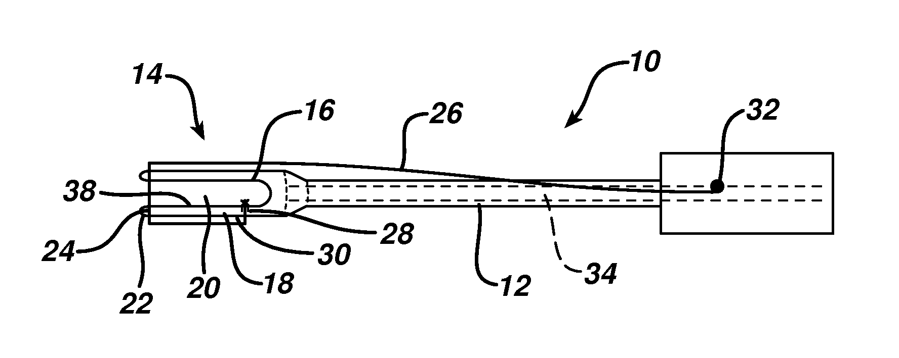
[0035]FIG. 1 depicts a graft implantation tool 10 according to the present invention. It comprises an elongated cannulated shaft 12 with a forked distal end 14. The distal end 14 comprises a first tine 16 and second tine 18 defining a space 20 therebetween. Each of the tines 16 and 18 has a distal terminal end 22 with a distal terminal notch 24. A length of suture 26 or other flexible material with suitable tensile strength spans the space 20 between the notches 24. It has a first end 28 affixed to the shaft 12 where the second tine 18 meets the shaft 12. From there it extends down along an exterior surface 30 of the second tine 18 enters the second tine notch 24, spans the space 20, enters the first tine notch 24 and then extends up the shaft 14 where it is secured in a suture retainer 32, which is shown for illustrative purposes as a simple cleat but any suitable retention can be employed as will be appreciated by those of skill in the art.

[0036]A cannulation 34 extends axially th...


PUM


Abstract

An instrument for placing a graft into a bone tunnel comprises an elongated shaft having a forked distal end comprising a pair of tines. A suture spans a space defined between the tines whereby the graft may be positioned between the tines and against the suture so as to be manipulated into the bone tunnel. The tendon folds about the suture, the suture having a releasable tension such that the instrument can be removed from the bone, leaving the tendon behind without the tendon hanging up on the suture.

Description

BACKGROUND[0001]This application relates to tissue manipulation instruments, and more particularly to instruments for implantation of graft tissue into a bone hole.[0002]In certain surgical procedures, such as tenodesis, a graft tissue is attached to a bone. For instance, in tenodesis a biceps tendon is detached from its attachment to the glenoid and is reattached to the humerus. In one popular method of reattachment a bone tunnel is created on the humerus and the detached tendon is pushed into the tunnel and then held in place via an interference bone screw implanted into the tunnel. Positioning the tendon in the tunnel can be tricky.[0003]In one method, the graft tissue is externalized from the patient and whip stitched to make a stiff construct at the termination of the tissue. The stiff construct may be pushed directly into tunnel using graspers or the like. A length of suture at the distal portion of the whip stitch may be used to pull the graft tissue into the tunnel. It is de...

Claims


Application Information

Patent Timeline
Patent Type & Authority Patents(United States)
IPC IPC(8): A61F2/08
CPCA61F2/0811A61F2/0805A61F2002/0858
Inventor PICCIRILLO, JUSTIN M.
Owner DEPUY SYNTHES PROD INC
Why Eureka
Try Eureka