Method to improve the resolution of time measurements and alignment in packet networks by time modulation

a time measurement and time modulation technology, applied in the field of methods, can solve the problems of insignificant impact, thermal noise, and can only be handled with normal averaging, and achieve the effect of improving the accuracy of the recovered clock

Active Publication Date: 2005-03-10
ZARLINK SEMICON LTD
View PDF23 Cites 7 Cited by
  • Summary
  • Abstract
  • Description
  • Claims
  • Application Information

AI Technical Summary

Benefits of technology

The invention further provides an apparatus for recovering timing information across a packet network at the receiver comprising a modulator at the sender for sending a modulat

Problems solved by technology

At the finest level, thermal noise, can only be handled with normal a

Method used


Image

  • Method to improve the resolution of time measurements and alignment in packet networks by time modulation
  • Method to improve the resolution of time measurements and alignment in packet networks by time modulation
  • Method to improve the resolution of time measurements and alignment in packet networks by time modulation

Examples


Embodiment Construction

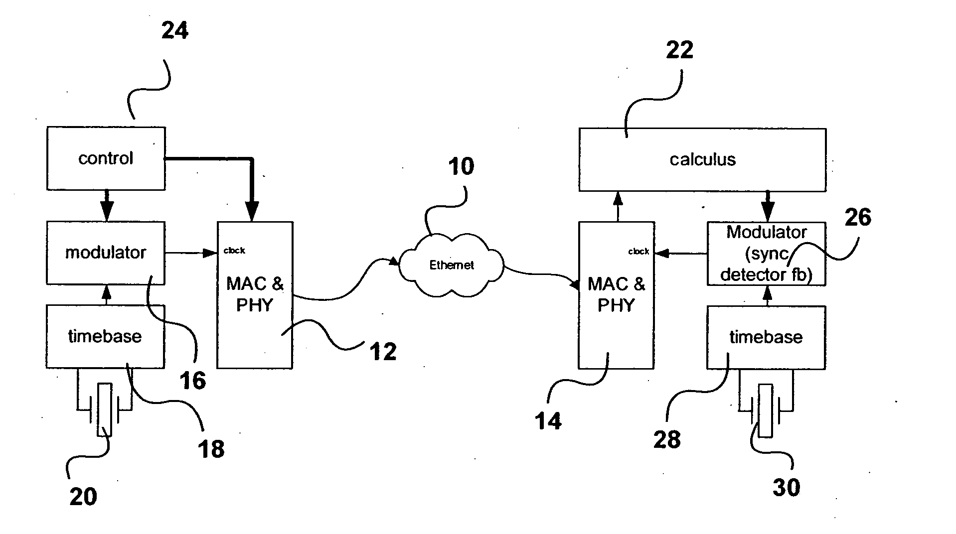
First the nature of the structured quantization effects will be discussed. In a first example, suppose in packet network there are only two Ethernet cards with a crosslink in-between, i.e. with no switches / routers. In such an environment it is not difficult to avoid quantization problems; a simple PLL can recover the frequency from one card and slave the other card. This PLL will force the clocks to be identical to each other in such a way that the delay variation becomes very small. However, over many nodes this approach is not feasible, for it denies the possibility of having switches with individual, independent clocks, in-between. A PLL provides a synchronous detection scheme, but that cannot be enforced over many quantizing nodes unless each node performs a synchronous detection scheme.

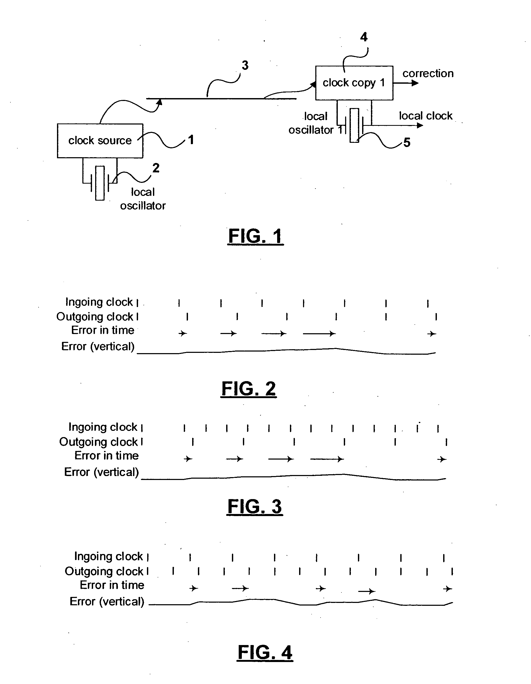
In FIG. 1, a clock source 1 with local oscillator 2 at the near end communicates with a clock copy unit 4 associated with a local oscillator 5 at the far end over network link 3. The correctio...


PUM


Abstract

A method of recovering timing information in a packet network is disclosed wherein a modulation scheme is used to transport additional information required for clock recovery between the sender and receiver across the network.

Description

FIELD OF THE INVENTION This invention relates to the field of digital communications, and in particular to a method of and apparatus for improving the resolution of time measurements in a packet network. BACKGROUND OF THE INVENTION There is a current trend for telecommunications and data technologies are nowadays to merge into a single environment, largely due to cost aspects. The preferred technology seems employs asynchronous networks, probably mainly due to market penetration, rather than the fact that asynchronous networks offer a higher quality solution. One particular aspect of asynchronous networks which creates problems for telecommunication services is the lack of accurate clock transport. There are a number of mathematical ways to solve the problem. Typical solutions used are based upon averaging, weighting, line fitting and combinations thereof. Still the final resolution remains limited due to a number of problems in the network. The nature of these problems is such t...

Claims


Application Information

Patent Timeline
IPC IPC(8): H04J3/06H04L7/033H04L7/04H04L7/00H04L27/00
CPCH04J3/0632H04J9/00H04J3/12H04L7/04H04L27/00
Inventor REPKO, WILLEM L.VAN DER VALK, ROBERTUS L.SIMONS, PETRUS W.ROOS, STEVEN
Owner ZARLINK SEMICON LTD
Why Eureka
Try Eureka