Push-push mechanism, in particular for card readers

Inactive Publication Date: 2013-10-29
AMPHENOL TUCHEL ELECTRONICS
View PDF24 Cites 0 Cited by
  • Summary
  • Abstract
  • Description
  • Claims
  • Application Information

AI Technical Summary

Benefits of technology

The present invention is about a push-push mechanism that uses a control cam with a spring-loaded control pin that is forcibly guided and tensioned along the wall. This design reduces the number of steps in the control cam and allows for a two-step control cam, which results in a lower height. In the reading position, the control pin is in a rest position formed by a V-shaped wall funnel and can save steps in this area. To reduce the height of the control cam and the control pin, the control pin length can be matched with the only present step-height, which will lead to a reduction in total height while also reducing the number of steps.

Problems solved by technology

The push-push mechanism shown here has on the one hand the disadvantage that many components are needed that in particular work together in a complicated way and if they in an inexact position, the function of the card reader will be impaired.
The height of the whole card reader due a push mechanism of this type is another disadvantage.
However the number of states and intermediate states as well as the reading state and the opening state only possible with many steps within the control cam.

Method used


Image

  • Push-push mechanism, in particular for card readers
  • Push-push mechanism, in particular for card readers
  • Push-push mechanism, in particular for card readers

Examples


Embodiment Construction

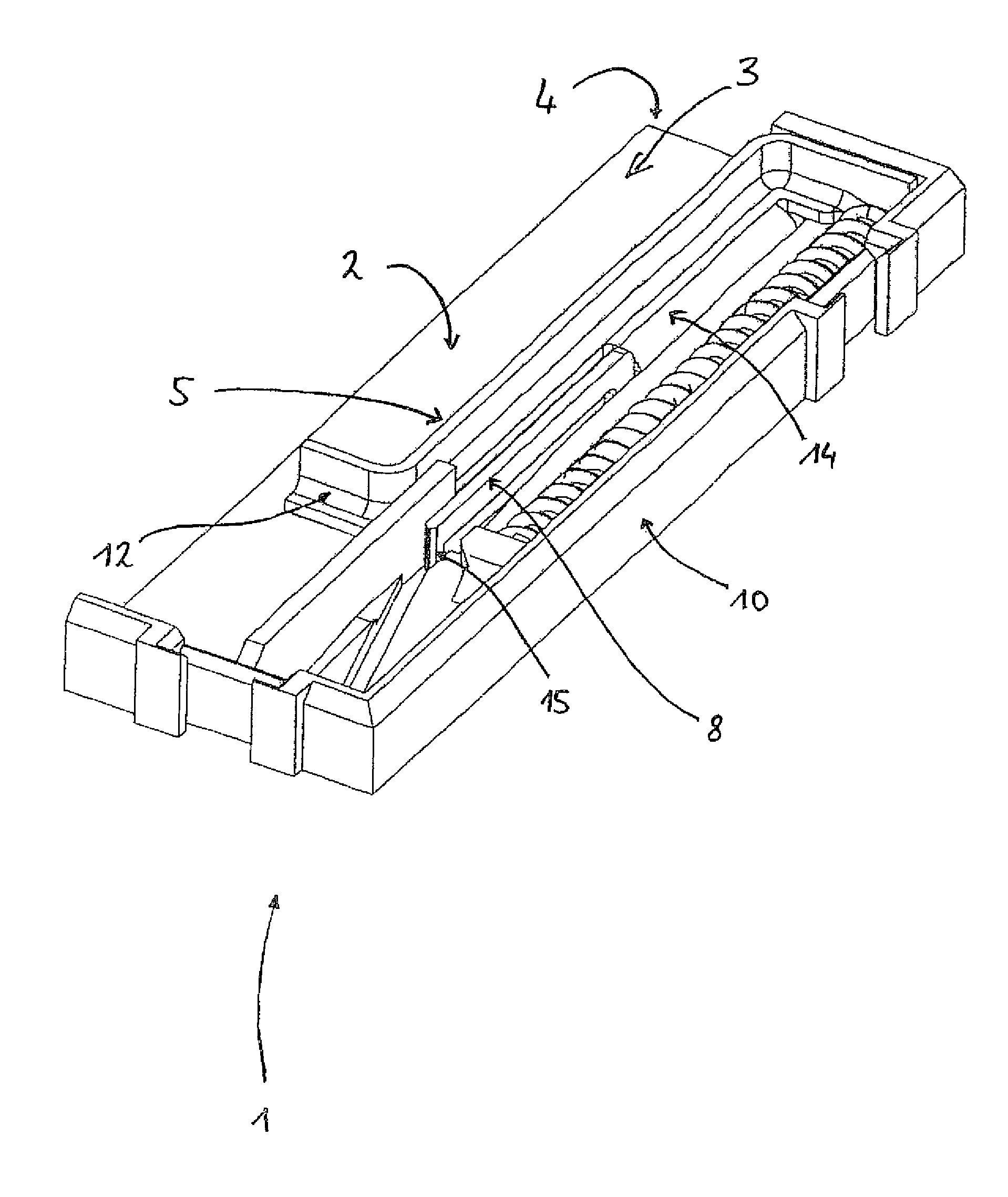
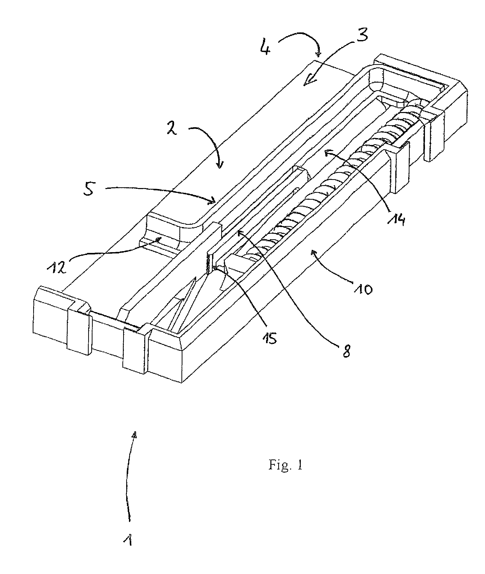
[0018]In the following first of all the slider 5 and the control pin 8 will be described.

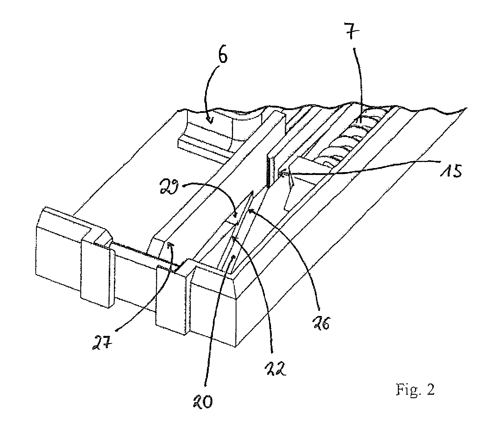
[0019]In FIG. 3 the slider 5 is in an initial position A and has a longitudinal arm 9, on which at both ends respectively a projecting cross arm 6, 16 is fixed. The first cross arm 6, which is in the card-receiving compartment and which projects into it, acts as the card stop 6. If a card is inserted into the card-receiving compartment 3, after insertion, it reaches the card stop 6 with the insertion side end, with which the slider 5 can be actuated. The second cross arm 16, which is fixed onto the insertion side end of the slider 5, projects in the opposite direction towards the side outer wall 10.

[0020]The cross arm 16 lies against the insertion side outer wall 11 with its front face, due to the pre-tension of the spring 7, which holds the slider 5 in this position. As can be clearly seen from FIG. 3, the spring-loaded control pin 8 is in its slack initial position and runs parallel to the lon...


PUM


Abstract

The invention concerns a push-push mechanism, particularly for a card reader with a control cam and a control pin, which engages with the control cam and is operatively connected with a slider, during which the transition of the control pin from the initial position to the reading position takes place by a first push and the transition from the reading position back into the initial position by a second push on the control pin and thus the slider, whereby the control pin is flexibly deflected during its actuation along the control cam.

Description

CROSS-REFERENCE TO RELATED APPLICATIONS[0001]The present application claims the benefit of International Patent Application no. PCT / EP2008 / 007554, filed Sep. 12, 2008, and German Patent No. 10 2007 044 170, filed Sep. 15, 2007, the entire disclosures of which are incorporated herein by reference.BACKGROUND OF THE INVENTION[0002]The invention relates to a push-push mechanism and thus the design of a control cam for a push-push mechanism. The invention thus concerns a push-push mechanism and particularly a control cam for a push-push mechanism, according to preamble in patent claim 1. In particular the invention concerns such push-push control cams that are suitable for application with a card reader, that includes a push-push mechanism. “Card” refers to chip-cards, smart cards and SIM cards, as well as other typical cards that are utilised in technology. Card reader refers to a card contacting device for application with a card. In the sense of the present invention, under push-push ...

Claims


Application Information

Patent Timeline
IPC IPC(8): H01R13/62
CPCG06K13/08G06K13/0806G06K13/085H01R13/635H01R12/7005
Inventor GOBEL, MARCO
Owner AMPHENOL TUCHEL ELECTRONICS
Why Eureka
Try Eureka