
Induction sealing

a tissue and induction sealing technology, applied in the field of induction sealing, can solve the problems of inefficient methods, inability to transfer effectors, and time-consuming for end effectors to cool down

Active Publication Date: 2013-10-29
TYCO HEALTHCARE GRP LP
View PDF80 Cites 137 Cited by
  • Summary
  • Abstract
  • Description
  • Claims
  • Application Information

AI Technical Summary

Benefits of technology

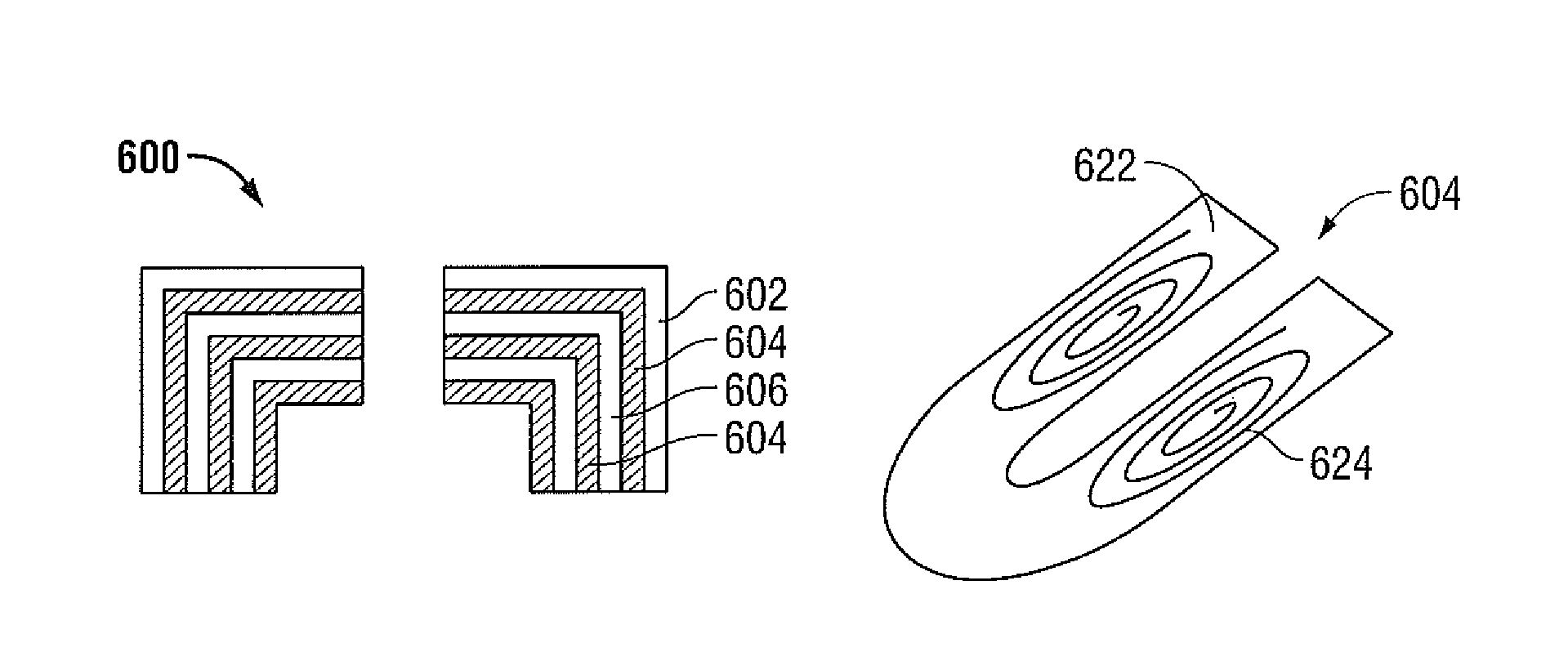
The present patent provides an end effector assembly for an electrosurgical instrument. The assembly includes a first jaw member and a second jaw member both having a support base and a sealing plate. The sealing plate has a first layer made of a non-stick material and a second layer with a coil. The second layer has two flex circuits with two corresponding coils that exhibit different properties when energy is applied to them. The technical effects of this design include improved sealing of tissue with reduced sticking of the sealing plate to the tissue, increased flexibility of the sealing plate, and better control of the sealing process.

Problems solved by technology

However, such methods may be inefficient in that all the heat generated in the end effector may not be transferred to tissue.
Further, when the end effector is heated during application of energy, once energy application is ceased, the end effector takes time to cool down which may affect tissue disposed between the jaw members.

Method used


Image

  • Induction sealing
  • Induction sealing
  • Induction sealing

Examples


Embodiment Construction

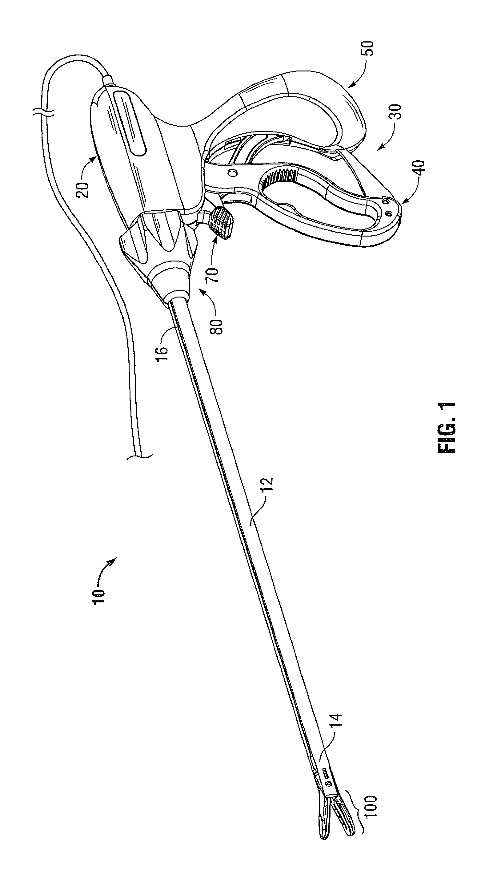
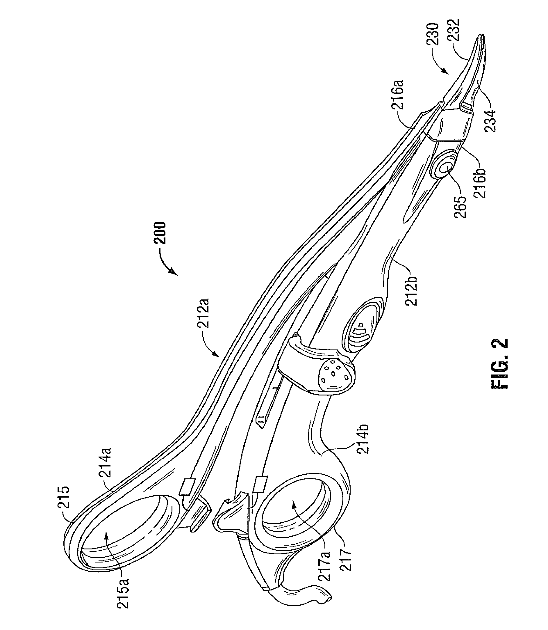
[0021]Particular embodiments of the present disclosure are described hereinbelow with reference to the accompanying drawings; however, it is to be understood that the disclosed embodiments are merely examples of the disclosure and may be embodied in various forms. Well-known functions or constructions are not described in detail to avoid obscuring the present disclosure in unnecessary detail. Therefore, specific structural and functional details disclosed herein are not to be interpreted as limiting, but merely as a basis for the claims and as a representative basis for teaching one skilled in the art to variously employ the present disclosure in virtually any appropriately detailed structure.

[0022]Like reference numerals may refer to similar or identical elements throughout the description of the figures. As shown in the drawings and described throughout the following description, as is traditional when referring to relative positioning on a surgical instrument, the term “proximal”...


PUM

PropertyMeasurementUnit
energyaaaaaaaaaa
electrical energyaaaaaaaaaa
electrosurgical energyaaaaaaaaaa

Abstract

An end effector assembly for use with an electrosurgical instrument is provided. The end effector assembly has a first jaw member having a support base and a sealing plate formed from a ferrous material. The end effector assembly also has a second jaw member including a support base, an electrical jaw lead and a sealing plate coupled to the electrical jaw lead. The sealing plate includes a first layer formed from a non-stick material and a second layer having a coil formed thereon.

Description

BACKGROUND[0001]1. Technical Field[0002]The present disclosure relates to an electrosurgical instrument and method for sealing tissue. More particularly, the present disclosure relates to an electrosurgical tool having opposing jaw members that include an induction coil and a ferrous layer configured to treat tissue by inductive heating.[0003]2. Background of the Related Art[0004]Electrosurgical forceps utilize mechanical clamping action along with electrical energy to effect hemostasis on the clamped tissue. The forceps (open, laparoscopic or endoscopic) include electrosurgical sealing plates which apply the electrosurgical energy to the clamped tissue. By controlling the intensity, frequency and duration of the electrosurgical energy applied through the sealing plates to the tissue, the surgeon can coagulate, cauterize, and / or seal tissue.[0005]Conventional tissue sealing procedures require imparting electrosurgical energy to an end effector having a pair of opposing jaw members. ...

Claims


Application Information

Patent Timeline
Patent Type & Authority Patents(United States)
IPC IPC(8): A61B18/04A61F2/00
CPCA61B18/085A61B2018/0013A61B2018/0063
Inventor HORNER, GLENN A.ROY, JEFFREY M.
Owner TYCO HEALTHCARE GRP LP
Learn More