
Compressed air foam technology

a compressed gas foam and compressed air technology, applied in medical science, dental surgery, fire rescue, etc., can solve the problems of complex systems and processes, complicated closed-loop control implementation, and document that does not deal with the problem of controlling different, etc., to achieve high and constant quality and simple implementation

Inactive Publication Date: 2013-11-05
SOGEPI SA
View PDF19 Cites 4 Cited by
  • Summary
  • Abstract
  • Description
  • Claims
  • Application Information

AI Technical Summary

Benefits of technology

The invention is a new technology for making compressed-gas foam (CAF) that can be used for fire extinguishing or decontamination purposes. The technology involves a foaming chamber that continuously produces high-quality foam. This invention simplifies the process of creating CAF and makes it more effective in fire extinguishing or decontamination applications. This patent also proposes a compressed-gas system that includes a foaming chamber for this purpose.

Problems solved by technology

A major problem for producing CAF is to control in an appropriate way the water flow and the air flow supplied to the mixing chamber so as to provide continuously foam having adequate properties for fighting fire and that remain stable over time.
The problem arises due to the fact that both the water and air supplied to the mixing chamber and the physical conditions in the pipes and nozzles for transporting and ejecting foam may vary.
Therefore, complex systems and processes are used for balancing the pressure of water and the pressure of air supplied to the mixing chamber or for adapting the pressure of air when the pressure of water varies.
However, this document does not give any detail on the way of controlling the different parameters, in particular pressure, volume flow rate and speeds / dwell time of air, water and foam so as to ensure that the mixing chamber provides continuously foam of good quality for extinguishing fire.
Further, the closed-loop control may be complicated to implement.
This document does not deal with the problem of optimizing the working conditions of the mixing chamber, but with the problem of allowing ejection of foam having a good quality despite the fact that foam is transported over long pipes.
However, this document does not deal at all with the problem of controlling the different parameters, in particular pressure, volume flow rate and speeds / dwell time of air, water and foam so as to ensure that the mixing chamber provides continuously foam of good quality for extinguishing fire.

Method used


Image

  • Compressed air foam technology
  • Compressed air foam technology
  • Compressed air foam technology

Examples


Embodiment Construction

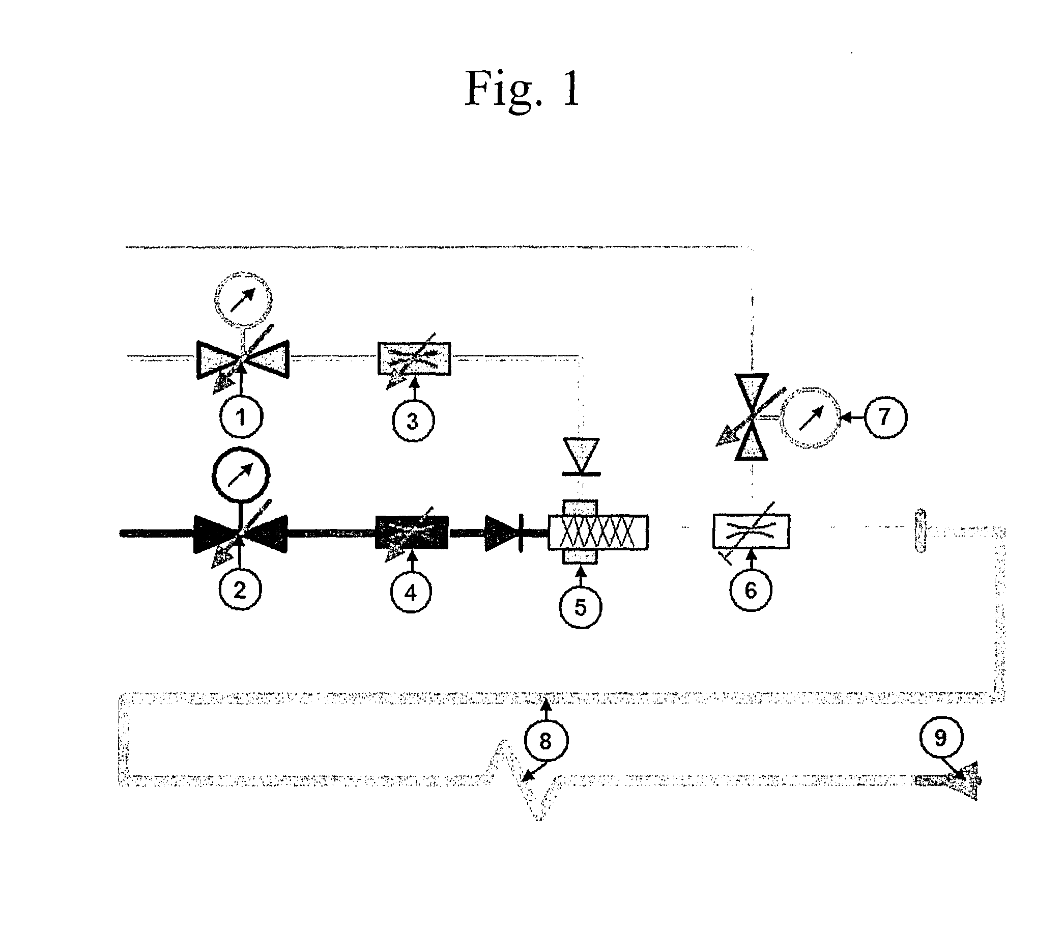
[0061]According to the invention, CAF is continuously produced by supplying both water containing at least a foaming agent and compressed air to a foaming chamber having an outlet for outputting. The mixture of foam agent and water is continuously supplied to the foaming chamber at a first constant pressure and at a first constant volume flow rate. Similarly, the compressed air is continuously supplied to the foaming chamber at a second constant pressure and at a second constant volume flow rate. Further, the pressure in the foaming chamber—that we will call hereafter foam mixing pressure—is regulated for maintaining said foam pressure constant, regardless of the possible lower pressure in the foam transporting line(s) connected at the outlet of the foaming chamber. The mentioned continuous production of foam and the continuous supply of compressed air and of the mixture of foam agent and water relates to the case in which the CAFS in use, i.e. in particular when the foam-ejecting d...


PUM


Abstract

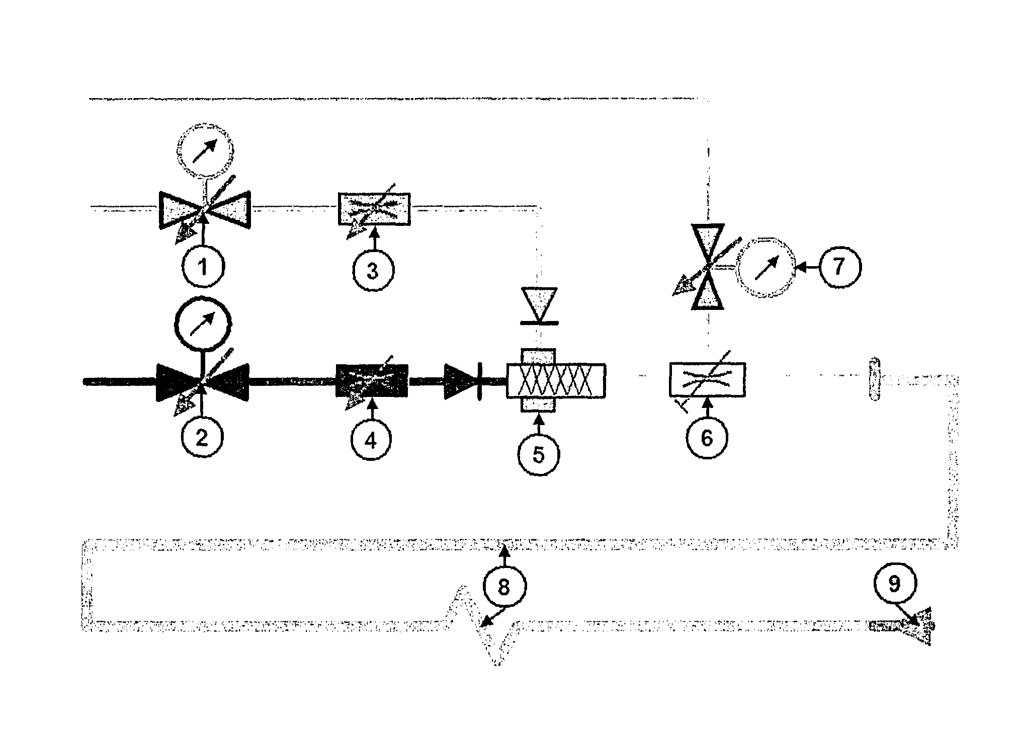
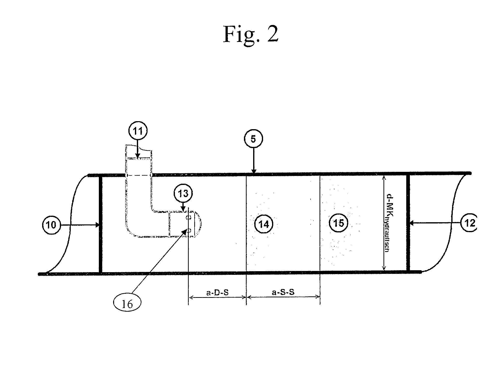
The method is for continuously producing compressed-air foam, notably for fire fighting or for decontamining, by supplying both compressed air and a mixture of water and at least a foaming agent to a foaming chamber (5) outputting foam to a nozzle (9) via a pipe (8). The mixture of foam agent and water and the compressed air are each continuously supplied to the foaming chamber (5) at a constant pressure and at a constant volume flow rate, e.g. by means of pressure regulators (1, 2) and of flow rate regulators (3, 4). The foam pressure is regulated at the outlet of the foaming chamber (5) for maintaining the foam mixing pressure in the foaming chamber constant, preferably by a self-operating valve (6). The foaming chamber can advantageously be of a static type comprising sieves.

Description

FIELD OF THE INVENTION[0001]The invention relates to a method for continuously producing compressed-gas foam, in particular compressed-air foam and a compressed gas foam system, in particular a compressed-air foam system, notably for extinguishing fire as well as a foaming chamber particularly adapted therefore.BACKGROUND OF THE INVENTION[0002]It is known in the art to fight fire with compressed-air foam (CAF). Typically, a foaming agent is added continuously to a water flow and the resulting flow of the mixture of foam agent and water is supplied to a foaming line or chamber which is also supplied with air pressure so as to generate foam. The foam exiting the foaming line or chamber passes through a rigid or flexible pipe to a nozzle for ejecting the foam onto the fire. The foaming line or chamber, also designated as a mixer or a mixing chamber, is usually of a static type, alternatively called motionless, i.e. without moving parts.[0003]Compressed air foam systems (CAFS) may be mo...

Claims


Application Information

Patent Timeline
Patent Type & Authority Patents(United States)
IPC IPC(8): A62C35/00A62C2/00A62C3/00
CPCA62C5/02
Inventor KRUGER, TINODORAU, GUNTER
Owner SOGEPI SA
Learn More