Method for the bonding of disk-shaped substrates and apparatus for carrying out the method

a technology of disk-shaped substrates and adhesive layers, which is applied in the direction of instruments, auxiliary welding devices, soldering apparatuses, etc., can solve the problems of reducing the quality of the output, misreading stored data, and variable thickness of the adhesive layer, so as to achieve short cycle time and high and constant quality of outpu

Inactive Publication Date: 2007-12-25
SINGULUS TECHNOLGIES AG
View PDF20 Cites 0 Cited by
  • Summary
  • Abstract
  • Description
  • Claims
  • Application Information

AI Technical Summary

Benefits of technology

[0016]It is the object of the invention to provide a method where the joining of the substrates takes place in a controlled manner, where variations of the thickness of the adhesive layer is small and gas inclusions between the substrates are virtually absent.
[0017]The method according to the invention allows a precisely controlled bonding step with short cycle time and high and constant quality of the output.
[0018]It is a further object of the invention to provide an apparatus which is suitable for carrying out the method according to the invention. The apparatus according to the invention is simple, unexpensive and reliable.

Problems solved by technology

In most cases the adhesive is applied to the upper side of the lower substrate whereupon the parallel upper substrate is lowered or dropped onto the adhesive layer and then pressed against the same as disclosed, e.g., in U.S. Pat. Nos. 6,265,578 A and 6,291,046 B. Major problems of this general method are variations in the thickness of the adhesive layer which is spread merely by mechanical pressure exerted by the often slightly warped substrates and the entrapment of gas which then forms inclusions or bubbles whenever areas where the adhesive and the upper substrate have not bonded properly are surrounded by bonded areas.
Both effects influence the optical properties of the disk and may cause misreading of stored data.
Although the problem of creating bubbles by entrapment is thereby reduced it could only be virtually completely solved in this way by applying high-vacuum which, however, would require long cycle times and expensive high performance vacuum pumps and is therefore unacceptable for economic reasons.
Also, longer exposure to vacuum may cause the formation of bubbles from gases solved in the adhesive under atmospheric pressure as it begins to outgas and it is usually not possible to wait for complete outgassing as this would increase cycle times even further beyond the economically acceptable.
However, this requires a relatively large chamber which exacerbates the problems mentioned above.
While spin coating provides adhesive layers of essentially constant thickness it does not solve the problem of gas inclusions.
Such balancing, however, requires precise control of angular velocity and pressure and is therefore difficult to achieve.
However, the control requirements are still difficult to fulfill.
This method, however, may as well lead to a varying thickness of the adhesive layer.
Also, entrapment of gas bubbles cannot be excluded.
This step is fraught with problems as explained above.
With this method the risk of gas entrapments is indeed very low, however, the pressure applied to the upper substrate decreases from the center outward which may cause a radially varying thickness of the adhesive layer.
Due to the fact that the release of the upper substrate is a function of several parameters which cannot be precisely controlled and reproduced like atmospheric pressure, contact surface and pressure in the suction holding device, elastic forces produced by the deformation of the upper substrate as well as the decreasing pressure between the substrates the step is not precisely controllable, in particular with respect to its timing.
This makes reliable execution of the bonding step with defined and short cycle times difficult to achieve.
It is, moreover, difficult to keep the space between the substrates reliably sealed and its evacuation through one of the central openings requires a complex apparatus.
With this method the motions of the substrates and, as a consequence, their relative positions cannot be precisely controlled which may lead to defects of the finished product.

Method used


Image

  • Method for the bonding of disk-shaped substrates and apparatus for carrying out the method
  • Method for the bonding of disk-shaped substrates and apparatus for carrying out the method
  • Method for the bonding of disk-shaped substrates and apparatus for carrying out the method

Examples


Embodiment Construction

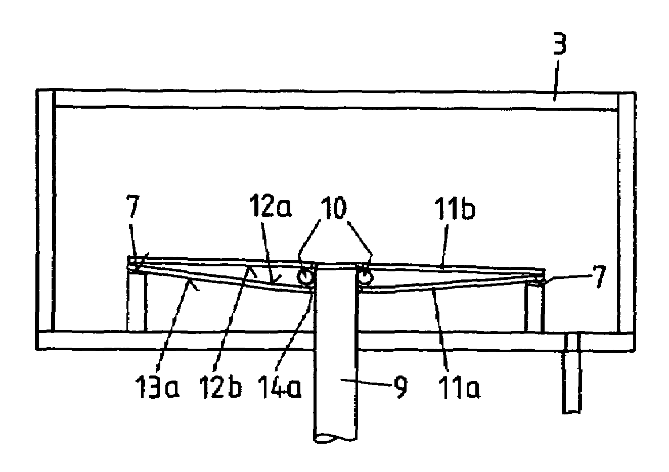
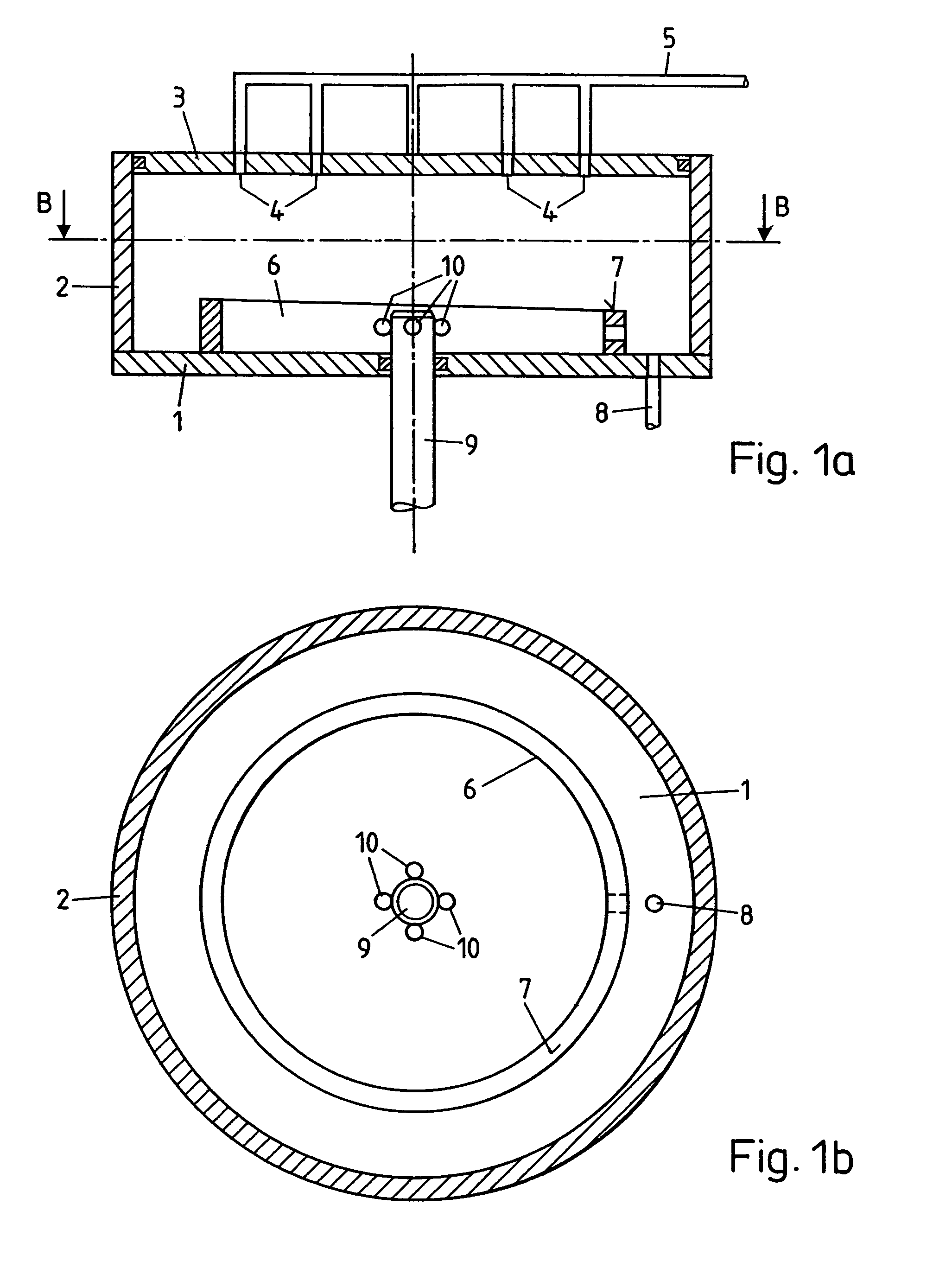
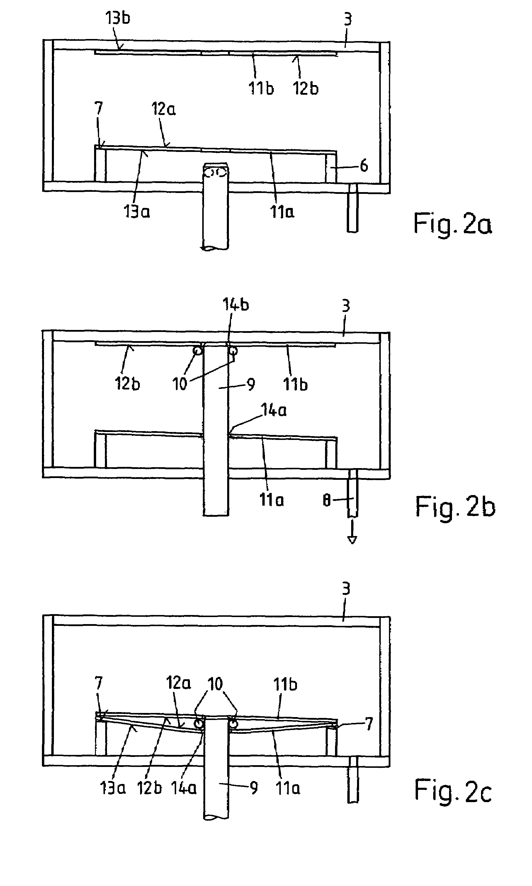
[0023]The apparatus comprises a cylindrical vacuum chamber with a base plate 1, a circumferential side wall 2 and a removable cover 3. Holes 4 which are connected via a suction line 5 to a suction pump (not shown) are distributed over the inside surface of the latter so the cover 3 can serve as a suction holding device. The base plate 1 carries a support 6, a web concentric with the side wall 2 whose annulus-shaped plane upward-facing support surface 7 is slightly slanted (to the right in FIG. 1a), defining a plane which encloses an angle of between 1° and 3°, preferably about 2° with the inside of the cover 3. From the bottom of the vacuum chamber, i.e. through the base plate 1 an evacuation line 8 leads to a vacuum pump (not shown). A central support pin 9 is extendable through the base plate 1. Its position can vary between a lower limit position where its tip lies below the support surface 7 and an upper limit position where the tip touches or nearly touches the cover 3. At a po...


PUM

PropertyMeasurementUnit
pressureaaaaaaaaaa
pressureaaaaaaaaaa
pressureaaaaaaaaaa

Abstract

A first substrate (11a) is positioned on a support surface (7) in a vacuum chamber with an upward-facing first bonding surface (12a) spin-coated with adhesive while a second substrate (11b) is held with downward-facing second bonding surface (12b) to a cover (3) by suction. While the vacuum chamber is being evacuated to a pressure of between 0.1 mbar and 2 mbar, a support pin (9) is extended through central openings (14a, 14b) of the substrates (11a, 11b) and then retracted with the second substrate (11b) released from the cover (3) and carried by radially extended balls (10). The support pin (9) is lowered to a position where the balls (10), acting against the first bonding surface (12a), deform the first substrate (11a). The first bonding surface (12a) being therefore slightly concave, the first and second bonding surfaces (12a, 12b) only touch close to their circumferences. Retraction of the balls (10) causes a spreading of the contact area radially inwards to cover the first and second bonding surfaces (12a, 12b) without entrapment of non-bonded areas. The substrates (11a, 11b) are then lifted by the support pin (9) with again extended balls (10) and pressed against the cover (3) and the vacuum chamber is aired.

Description

FIELD OF THE INVENTION[0001]The invention relates to a method for the bonding of disk-shaped substrates and an apparatus for carrying out the method. Method and apparatus are used in particular for the production of optical disks for data storage such as DVD disks.PRIOR ART[0002]DVD and similar disks usually comprise a lower disk-shaped substrate and an upper disk-shaped substrate, both with central circular openings, which normally consist of a plastic material like polycarbonate. At least the lower substrate carries a thin optically active, i.e. reflective or semi-reflective layer, usually consisting of a metal like Al, Au, Ag, Cu or an alloy, which carries the data. The upper substrate is bonded to the lower substrate by an adhesive, e.g., a UV-curable resin or a hot melt. The liquid adhesive is usually applied to the lower substrate before the substrates are joined and cured after the joining step. Alternatively, use of adhesives in the shape of flexible sheets has been proposed...

Claims


Application Information

Patent Timeline
Patent Type & Authority Patents(United States)
IPC IPC(8): B32B37/10B29C35/08B29C65/00B29C65/48B29C65/78B32B37/12G11B7/24G11B7/26
CPCB29C65/7847B29C66/342B29C66/452B32B37/003B32B38/1866G11B7/24038G11B7/26B29C66/001B29C65/48B29C65/00B29C65/485B29C2035/0827B29K2069/00B29L2017/005B32B37/12B32B2309/06B32B2309/68B32B2429/02B29C65/4845B29C65/4815B29C66/8322B29C66/71B29C66/72321B29C66/1122B29C65/7811
Inventor EISENHAMMER, THOMASOU-YANG, JEFF
Owner SINGULUS TECHNOLGIES AG
Why Eureka
Try Eureka