Vapor chamber semi-shearing forming method

A technology of vapor chamber and cover plate, which is applied in the direction of semiconductor devices, indirect heat exchangers, lighting and heating equipment, etc. It can solve the problems of weak support and negative impact on the strength of the vapor chamber, so as to maintain integrity and avoid deformation effect

Active Publication Date: 2020-02-11
DONGGUAN LINGJIE PRECISION MACHINING TECH CO LTD
View PDF7 Cites 3 Cited by
  • Summary
  • Abstract
  • Description
  • Claims
  • Application Information

AI Technical Summary

Problems solved by technology

The surface of the internal structure obtained in this way is smooth and the supporting effect is weak, which has a negative impact on the strength of the vapor chamber

Method used


Image

  • Vapor chamber semi-shearing forming method
  • Vapor chamber semi-shearing forming method
  • Vapor chamber semi-shearing forming method

Examples


Embodiment 1

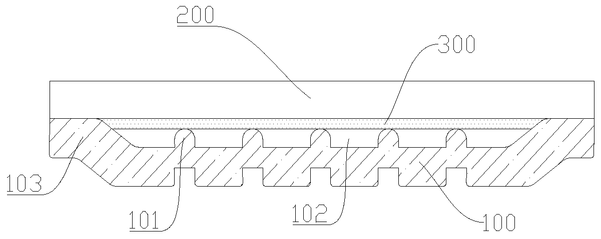
[0033] figure 1 and figure 2 A vapor chamber according to the method of the present invention is schematically shown. The vapor chamber stamping method provided by the present invention includes the following steps:

[0034] (1) Two plates are provided, which are divided into the first cover plate 100 and the second cover plate 200 . The first cover plate 100 and the second cover plate 200 are square copper plates with the same size.

[0035] (2) Use a punch press to perform semi-shear punching on the middle part of the first cover plate 100 from the bottom to form a plurality of support columns 101 . There are gaps 102 between the support columns 101 , and the gaps 102 between the plurality of support columns 101 communicate with each other. After the half-shear stamping, there is a certain connection thickness between the support column 101 and the starting plate surface. In this way, the first cover plate 100 can be prevented from being broken due to the half-shearing ...

Embodiment 2

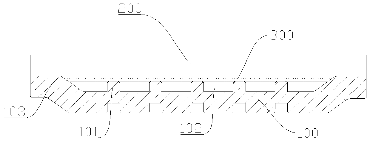
[0043] image 3 and Figure 4 Schematically shows another vapor chamber according to the method of the present invention. The difference from Embodiment 1 is that the first cover plate 100 and the second cover plate 200 are both metal aluminum plates, and the first cover plate 100 is The half-cut support column 101 is a square cylinder, and the support column 101 is in contact with one side of the liquid-absorbent core 300 .

[0044] In addition, in the process, the liquid-absorbent core 300 is fixed at the middle position of the second cover plate 200 by sintering, and when the first cover plate 100 and the second cover plate 200 are attached to each other, the liquid-absorbent core 300 is just in line with the embedded fit in the inside of the welding flange edge 103. In addition, the welding method of the second cover plate 200 adopts diffusion welding.

Embodiment 3

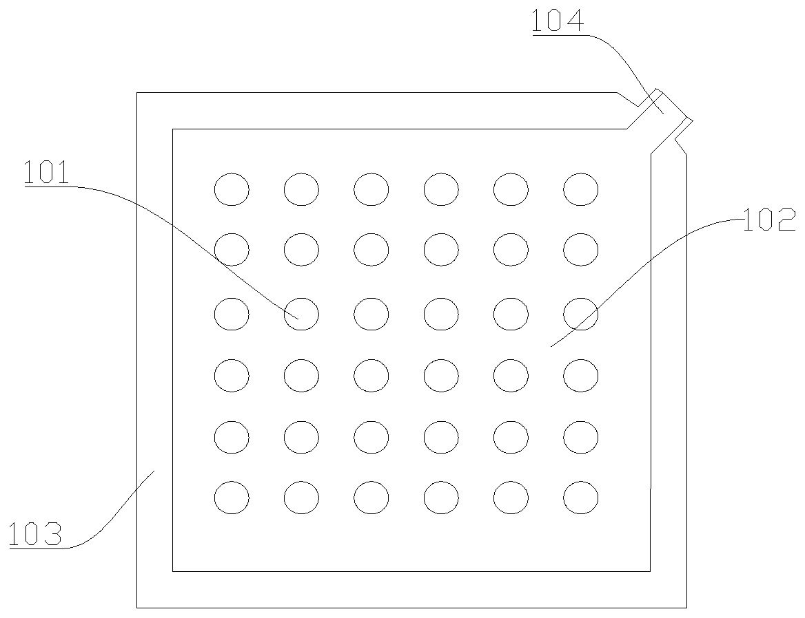
[0046] Figure 5 and Figure 6 Schematically shows the structure of the first cover plate 100 of another heat chamber according to the present invention. The arrangements are different. In this embodiment, the four support columns 101 are close to each other to form a local support unit. The multiple local support units are distributed in an array, and there are gaps 102 inside the local support units, and there are gaps 102 between the multiple local support units. The support column 101 is in contact with one side of the liquid-absorbent core 300 . In addition, the edge of the second cover plate 200 is processed into a positioning block 201 through a bending process, and the positioning block 201 can engage with the welding flange 103 on the edge of the first cover plate 100 .


PUM


Abstract

The invention discloses a vapor chamber semi-shearing forming method. The vapor chamber semi-shearing forming method includes the following steps of providing a first cover plate and a second cover plate, forming a plurality of supporting columns in the middle of the first cover plate in a semi-shearing stamping mode, performing semi-shearing on the edge to form a welding flange edge, reserving anair outlet, buckling the second cover plate on the first cover plate and performing sealing along the welding flange edge after a heat adsorption core body is adsorbed into the first cover plate or the second cover plate to form a cavity, vacuumizing the cavity after injecting working fluid into the cavity through the air outlet to form negative pressure, and finally sealing the air outlet to prepare a vapor chamber. The vapor chamber cover plates are manufactured in the semi-shearing stamping mode, production cost is reduced, and the environmental protection is facilitated; by arranging positioning blocks, the positioning precision is ensured, and the percent of pass of the product is improved; and through a welding mode, the production cycle of the whole technological process is greatlyshortened, and efficient production is realized.

Description

technical field [0001] The invention relates to the technical field of vapor chamber manufacturing, in particular to a method for forming a vapor chamber by half-shearing. Background technique [0002] With the rapid development of 5G wireless communications, radar, drones, satellites and other fields, the application prospects of high-power radio frequency chips are becoming more and more broad. The operating speed of the chip will be greatly improved, and the heat generated by it will also increase accordingly. Ensuring its stable operation has become the top priority. Therefore, the demand and challenges for the vapor chamber will also follow, and its industrial layout will be accelerated. There is no delay. [0003] The upper and lower covers of the traditional vapor chamber are manufactured by wet etching. This method uses a large amount of oxidants and strong acids, and the waste water generated causes great pollution to the environment. At the same time, this process...

Claims


Application Information

Patent Timeline
Patent Type & Authority Applications(China)
IPC IPC(8): F28D15/02F28D15/04H01L21/48H01L23/367
CPCF28D15/0283F28D15/04H01L21/4878H01L23/3672
Inventor 李海禄梁平平李学华
Owner DONGGUAN LINGJIE PRECISION MACHINING TECH CO LTD
Why Eureka
Try Eureka